LiniStepper v1. Microstepping Stepper Motor Driver Kit
How to build it! Assembly Instructions for the Original,
Version 1 Kit. (Version 2 instructions are
also available)
You need the usual small electrical tools and soldering iron with FINE tip,
preferably temperature controlled. Although assembly is very simple and clearly
laid out, it is expected that you have good soldering skills and some experience
with closely packed circuit boards.
* HEATSINK! Cut and drill the alloy heatsink bracket or drill and tap
the CPU fan
Please note that this is the heatsink bracket and is not a heatsink
itself. A (much) larger heatsink should be clamped to the bracket. One advantage
of using a CPU fan is that it can be directly mounted..
CAUTION: The Linistepper requires suitable, large heatsinking. Such as standard chunky aluminum/alloy heatsinks with fins. For additional heat dissipation use a bigger heatsink with extra fins, or a small computer fan to remove the excess heat. (steel is not a suitable heatsink)
Use 25mm x 25mm x 3mm alloy angle, available at any hardware store. US size is 1" x 1" x 1/8". You need 100mm (4") length for larger motors like 1A and above, but can use a shorter piece (like the same width of the board) for smaller motors. See the picture for the 100mm example. Thanks to George Richards for sending along his PDF bracket cutting guide
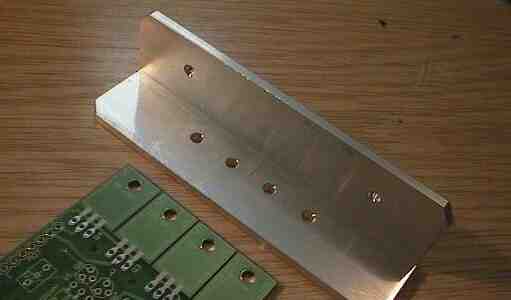
Drill 4 holes to suit the 4 PCB holes, use the PCB as a template held against the bracket or CPU fan heatsink and use a ballpoint pen to mark the holes. See the picture for the positioning of the bracket. Drill the 4 holes 3mm or 1/8 inch diameter.
Drill 2 or 3 more holes on the other wall of the angle bracket which allow it to be bolted to the heatsink. Small motors may not need the additional heatsink, the bracket might be enough once mounted in a metal box etc.
With a 1A motor you need a big heatsink, about 1.5'C/watt as a minimum size, (that is about 400g weight (a pound) of alloy) It will be cheaper to use a smaller heatsink and a cheap computer fan (fans available for under $2 these days). Remember to heat-test your heatsink for at least 1/2 hour at full power to make sure that the 4 main transistors don't get over 25'C rise (not over 45'C total).
 CPU Fan Option
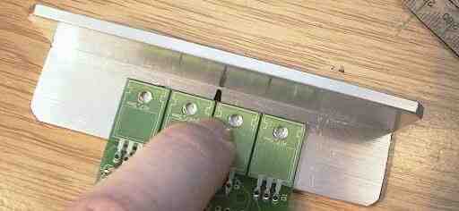
If you use a CPU heatsink/fan, you can mount the TIP 122 power transistor's to the face that would normally press against the CPU, and mount the bottom edge of the heatsink fins to the top of the Lini PCB where the transistors would normally be bolted (see the picture below).
Check the length of the leads to see where the holes in the CPU fan heatsink face should be placed.The best location is just a bit above center.
Use the PCB as a guide to mark the locations for the power transistors mounting
holes, then center punch and drill.
See:
http://www.piclist.com/techref/taps.htm#drillcalc for
information on tap and drill sizes.
Again, using the PCB as a guide, mark 2 or 4 holes on the bottom fins of the CPU fan heatsink to use in mounting the PCB. Drill through several fins, then carefully tap through those fins to provide threads for your mounting bolts to grip into. Go deeper than you think you need to because each fin only provides a few threads to hold the bolt.
* Inspect the board Check the board is ok, check for broken tracks, filled solder holes etc.
* Check all the bits are there Check through the parts and compare to the parts list to see if there are parts missing, damaged or exchanged for different types. If you are building a special version of the board, like a high current one that needs different resistors, make sure you have the extra parts before you start.
| Part | Package | Photo | Description | |
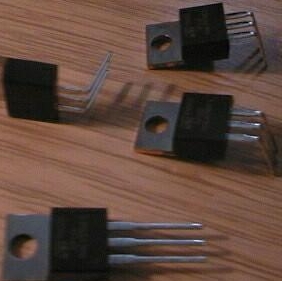
| Q1-4 | TIP122 | 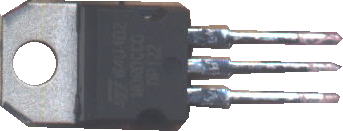 |
Power transistors | |
| Q5-8 | TO-92 | 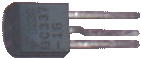 |
Switching Transistors | |
| IC1 | DIP 18 | 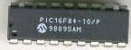 |
PIC Microcontroller | |
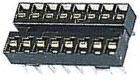 |
Socket | |||
| R1-2 | 3 Watt | 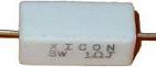 |
Power Resistors | |
| R3-6 | not supplied | 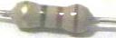 |
used to tune for higher power | |
| R7-31 | 1/4 Watt | Resistors | ||
| C1 | big radial | 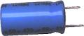 |
470uF Electrolytic Capacitor | |
| C2,4 | Disk | 22pF Capacitors No longer needed or supplied |
||
| C3 | blob | 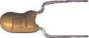 |
10 to 22uF Tantalum Electrolytic Capacitor | |
| C5,6 | disk/blobs | 2.2 to 4.7uF Electrolytic Capacitors | ||
| D1-6 | axial glass | 1N4148 Diodes | ||
| XT1 | blue disk |  |
ceramic resonator Now a three lead resonator (eliminates C2 and C4) |
|
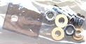 |
Misc: Nuts, bolts, washers, mica insulators, heatsink grease pin headers, connectors, etc... |
* Solder the flat parts first.
This means resistors and diodes mainly.
Resistors
The resistors come in two types, 4 band and 5 bands, referring to the number
of colors on the bands. The kit may come with 5 band metal film resistors,
1% tolerance. Make sure you get the resistor values right BEFORE soldering
them in!
Do them in blocks of 4 or 5, the way the board is layed out. Insert the 4 resistors, put the colours the same way around making them easier to read, and splay the legs a bit to hold them in. Then invert the board and solder them in, finishing by removing the excess legs with fine point wire clippers.
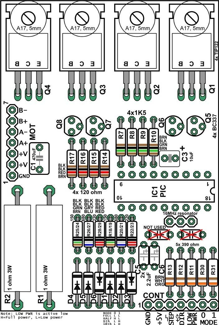
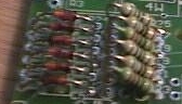 Notice below the 6 "microstep tuning" resistors are mounted
on a bit of an angle to make them fit.
Notice below the 6 "microstep tuning" resistors are mounted
on a bit of an angle to make them fit.
Diodes
There are 6 diodes, WATCH OUT the diodes are NOT all the same way around,
they are layed out like in the circuit diagram:
--   |--
--   |--
--|   --

--   |--
--   |--
--|   --
The diodes MUST be the correct way around.
PIC Chip
First solder in the socket, making sure the notch end of the socket goes
toward the OUTSIDE of the board. The socket and the PIC must be the correct
way around!
Don't insert the PIC into the socket until the board is complete.
Oscillator/PIC parts
The PIC has a 16 MHz ceramic resonator which is now supplied as a three lead
unit that does not require the 2 small 22pF caps C2 and C4. Insert the the
resonator, keeping the writing on the parts pointed out so you can read it.
Insert the tantalum cap C3 next to the PIC. It MUST be in the correct way around, the + lead (which is the longer lead; the mark is hard to read on the cap) goes toward the board edge.
Other caps
The two small caps (C5,C6) and large electro cap (C1) can be inserted next.
All these caps MUST be inserted the correct way around! In each case
the + of the cap goes towards the big transistors.
Connector pins
Make sure these are cut into 2 strips of 7 pins, and solder in as shown in
the picture above. These have a low melting point, and must be soldered QUICKLY
with a clean soldering iron tip and fresh solder. It may help to clamp the
pins with a metal clamp etc to keep them cool when soldering.
Small transistors
The 4 small transistors Q5,6,7,8 are inserted as shown on the board itself.
Don't push them all the way down, leave about 4mm of legs above the board.
Solder each one by one leg only to start with, and then you can straighten
them and make them look neat before soldering the other legs.
* The big transistors need special attention
Once the flat parts are all done you can do the fiddly stuff, of which the
most fiddly are the power transistors.
* mount the heatsink bracket, or the CPU fan, to the board with 2 bolts. For the bracket, use the outside two, for the fan, the inside two. The bracket or fan goes on TOP of the board.
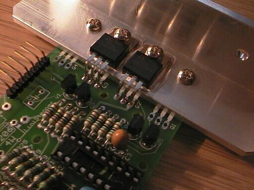
* once the bracket or fan is secured, it's time for the 2 middle transistors to go in;
* Do the middle 2 transistors first, the outer 2 after.
IMPORTANT!
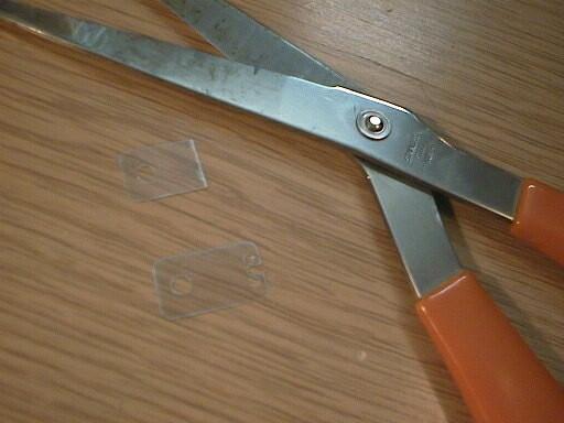
After insterting all 4 of the power transistors make sure the clear
mica washers and cream insulator washers are in correctly. This
can be checked by testing that the metal tag of the transistors ARE
NOT CONNNECTED to the heatsink (use an ohm meter).
Next are the big 3W resistors
mount these about 6mm above the board to keep them cooler, and also this
provides a place to attach the CRO leads if you wish to view the current
waveform.
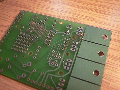
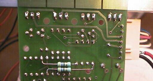
IMPORTANT!
You must add two 470 ohm resistors on the bottom of
the board and these must be added exactly as shown in this photo (bend
and cut the leads to suit and then solder);
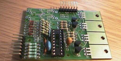
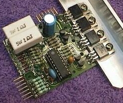
Finally you should have a completed board!
Check the board carefully with the photos and board layout diagram. Be sure
to check the following:
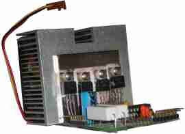
Hopefully it will look something like this:
Now you can move on to using the board and keeping it cool. at http://www.piclist.com/io/stepper/linistep/lini_use
We very much recommend using our Linistepper "4 AXIS / Mode / 555 / PWR" kit to drive the Linistepper.
-end
Questions: +
After thinking about your question for a while, we decided to make a set of 3 boards available for $35.00. These are VERY well made boards and are certainly worth the price IF you have a well stocked inventory of parts in your scrap box to populate them. With the kit of parts only $25 each quantity 3, I don't think you will ever find the parts for less from another vendor. +
Questions:
| file: /Techref/io/stepper/linistep/lini_bld.htm, 17KB, , updated: 2009/11/9 14:40, local time: 2025/10/23 01:37,
owner: RB-ezy-Q33,
216.73.216.114,10-3-244-150:LOG IN
|
| ©2025 These pages are served without commercial sponsorship. (No popup ads, etc...).Bandwidth abuse increases hosting cost forcing sponsorship or shutdown. This server aggressively defends against automated copying for any reason including offline viewing, duplication, etc... Please respect this requirement and DO NOT RIP THIS SITE. Questions? <A HREF="http://www.piclist.com/techref/io/stepper/linistep/lini_bld.htm"> LiniStepper, lini, stepper, linear, 6th microstep, linear microstepping stepper motor driver, constant current linear driver, circuit Linistepper boards, LiniStepper kit, hobby stepper, robot stepper driver kit, CNC stepper driver kit</A> |
| Did you find what you needed? |
|
o List host: MIT, Site host massmind.org, Top posters @none found - Page Editors: James Newton, David Cary, and YOU! * Roman Black of Black Robotics donates from sales of Linistep stepper controller kits. * Ashley Roll of Digital Nemesis donates from sales of RCL-1 RS232 to TTL converters. * Monthly Subscribers: Gregg Rew. on-going support is MOST appreciated! * Contributors: Richard Seriani, Sr. |
|
The Backwoods Guide to Computer Lingo |
.