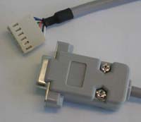
Ashley Roll has put together a really nice little unit here. Leave off the MAX232 and keep these handy for the few times you need true RS232! Plugs into any 0.1" header to connect to your circuit. Perfect for the BASIC Stamp or other microcontroller appications.

User comments:
Brady Palmquist says: "James...got your RS232/TTL cable today. FAST! And it looks great. Will work great for programming radios. Thanks VERY much."
The RLC units can allow you to talk to a wide range of devices, to adjust, fix, or re-program them.
Monitor ECS Erik Hanson reports that with a little modification, the RLC-1 can be made into an ECS port converter cable for data sent by the Sony DAS (Digital Alignment Software) to control all aspects of the operation of the monitor.
SONY: The RLC-1 must be modified by swapping the first two pins in the socket to match those on a SONY monitor. The pinout of the connector on Sony monitors is, from top to bottom:
PinRLC
Color
Signal
Description1. Black GND Connects to pin 1. GND on the Monitors ECS port 2. White +5V Connects to pin 2. STBY +5VDC on the Monitors ECS port 3. Yellow Tx/Dout Driven by the Monitor to send data to the PC (connects to pin 3. "RX" on the Monitors ECS port 4. Red Rx/Din Driven by the PC/RLC to send data to the Monitor (connects to pin 4. "TX" on the Monitors ECS port 5. Blue RTS unused, may need to be shorted to CTS depending on your PC and the software used. 6. Green CTS unused, may need to be shorted to RTS depending on your PC and the software used. We now have an ECS specific version of the RLC1 (called the RLC2) which had the correct pinout for a SONY monitor. It's the same other than that; if we are out of stock on RLC1's and you are in a hurry, order an RLC2 and swap pins 1 and 2.
PANASONIC: The RLC-1 must be modified by swapping the 3rd and 4th pins in the socket to match those on a Panasonic monitor. The pinout of the connector on Panasonic monitors is, from top to bottom:
PinRLC
Color
Signal
Description1. White +5V Connects to pin 1. STBY +5VDC on the Monitors ECS port 2. Black GND Connects to pin 2. GND on the Monitors ECS port 3. Red Rx/Din Driven by the PC/RLC to send data to the Monitor (connects to pin 3. "TX" on the Monitors ECS port 4. Yellow Tx/Dout Driven by the Monitor to send data to the PC (connects to pin 4. "RX" on the Monitors ECS port 5. Blue RTS unused, may need to be shorted to CTS depending on your PC and the software used. 6. Green CTS unused, may need to be shorted to RTS depending on your PC and the software used.
(These pinouts are known to be correct for most supported monitors, but some can be different . If you aren't sure of your monitor, use a meter to read the voltage levels on the pins of the monitors ECS port and email those readings to us with the monitor model)Network Gear Another use for the RLC is to communicate with onboard programming or console ports inside Network Switches, Routers, and Storage systems:
- QNAP TS-409 NAS http://www.cyrius.com/debian/orion/qnap/ts-409/serial.html documents the connector pinout as follows from left to right looking from outside toward the center of the board: GND, RX (TX from RLC1), VCC, TX (RX to RLC1). The connector supplied with the RLC1 must be replaced with a JST PHR-4^ connector.
- RouterStation OpenWRT http://www.ubnt.com/wiki/RouterStation_OpenWRT_SW_Setup_Guide#Connecting_to_RouterStation J3 is pin1 - 3.3V, pin2 - S_IN (RX), pin5 - S_OUT (TX), pin6 - GND, so the RLC-1 connector would need to be re-arranged to that pinout.
Hard Drives The RLC unit can be used to talk to a Seagate 7200.11 hard drive and fix a common problem that causes the drive to get "stuck" in busy mode. See
http://sites.google.com/site/seagatefix/Home for detailed instructions. The converter he uses is no longer available (last we checked) but the RLC does nicely intead.
Also:
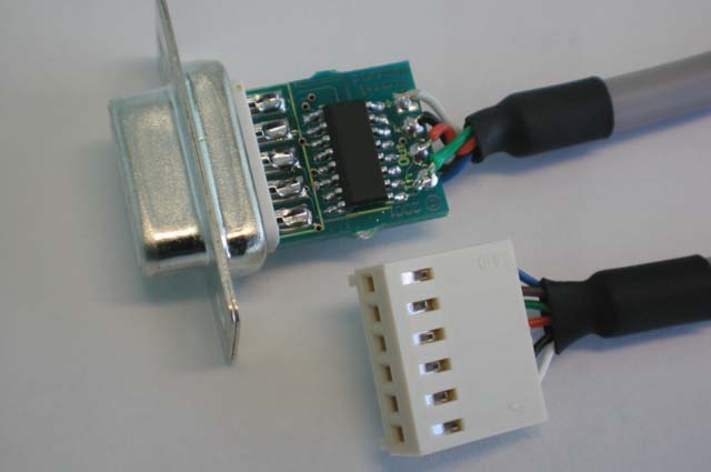
Shown With Backshell removed
RLC-1 Datasheet
Digital Nemesis Pty Ltd |
||||||||||||||||||||||||||||||||||||||||||||||||||||||||||||||||||||||||||||||||||||||||||||||||||||||||||||||||||
Introduction |
||||||||||||||||||||||||||||||||||||||||||||||||||||||||||||||||||||||||||||||||||||||||||||||||||||||||||||||||||
|
||||||||||||||||||||||||||||||||||||||||||||||||||||||||||||||||||||||||||||||||||||||||||||||||||||||||||||||||||
| ©
Digital Nemesis Pty Ltd, 2001. Brisbane, Australia. www.digitalnemesis.com |
||||||||||||||||||||||||||||||||||||||||||||||||||||||||||||||||||||||||||||||||||||||||||||||||||||||||||||||||||
Questions:
Comments:
See also:
Other sources:
| file: /Techref/io/serial/RCL1.htm, 21KB, , updated: 2020/4/20 10:27, local time: 2025/10/18 13:58,
216.73.216.114,10-3-244-150:LOG IN
|
| ©2025 These pages are served without commercial sponsorship. (No popup ads, etc...).Bandwidth abuse increases hosting cost forcing sponsorship or shutdown. This server aggressively defends against automated copying for any reason including offline viewing, duplication, etc... Please respect this requirement and DO NOT RIP THIS SITE. Questions? <A HREF="http://www.piclist.com/techref/io/serial/RCL1.htm"> RLC-1 RS232 TTL 3V Level Converter in a DB9 backshell</A> |
| Did you find what you needed? |
|
o List host: MIT, Site host massmind.org, Top posters @none found - Page Editors: James Newton, David Cary, and YOU! * Roman Black of Black Robotics donates from sales of Linistep stepper controller kits. * Ashley Roll of Digital Nemesis donates from sales of RCL-1 RS232 to TTL converters. * Monthly Subscribers: Gregg Rew. on-going support is MOST appreciated! * Contributors: Richard Seriani, Sr. |
Welcome to www.piclist.com! |
.