This page is for the 3rd Version of the "4 Axis" kit. It has been replaced by a newer version. The original and 2nd version documentation is also available.
The "4 axis / 555 / Mode / Power" kits for the Linistepper can provide all of the following:
Options: Combining all these functions on one printed circuit board was more cost effective than making multiple different boards, but you may not wish to populate all the parts of the board; for example, if you run small 8 to 10 volt motors, a single ATX PC power supply can provide both +12 volt motor supply and +5 volts for the linisteppers, so the voltage regulator section would be redundant. To make different configurations easy, we sell the kit(s) in seperate parts:
| Kit |
Parts |
Specs |
QTY |
Description |
| PCB:
|
||||
| PCB1 | Two Layer, plated through holes, silkscreen, soldermask | 1 | The printed circuit board only: | |
| DB-25 PC Parallel Port kit:
|
||||
| J1 | DB25, Femail, Solder tail | 1 | DB25 pushes on to edge of PCB | |
| CBL | DB25,Male-Male | 1 | Cable to connect to PC Parallel Port | |
| Mode Switches and Resistor:
|
||||
| S1 | 9 DIP | 1 | DIP switch, PCB mount, 9 position | |
| R3 | 10 SIP, 1kOhm | 1 | Resistor network | |
| Relay driver and PCB mount relay
kit: #4Axis2RLY Not yet available.
|
||||
| 555 Pulse kit:
|
||||
| U2 | NE555, DIP 8 | 1 | NE555 | |
| R1,R2 | TRIM, 500K | 2 | R2 changes frequency, R1 changes duty cycle AND frequency | |
| C1,C2 | CERAMIC, 0.1 RADIAL, 22nF | 2 | Capacitors | |
| R9 | CARBON, 1/4 WATT AXIAL, 330 Ohm | 1 | Resistor couples output to X axis Step | |
| +5 Power kit:
|
||||
| U1 | LM-7805 | 1 | 5 Volt regulator | |
| TB1 | 3 Pin, 0.2 | 1 | Terminal Block | |
| D1 | 1N4001, 1A, AXIAL | 1 | Reverse protection diode | |
| C1 | ELEC, 0.2 RAD, 1000uF | 1 | Main supply filtering | |
| C2 | ELEC, 0.1 RAD, 10uF | 1 | Main output filtering | |
| C5 | CERAMIC, 0.1 RAD, 100nF | 1 | Secondary output filtering. 22nF supplied. | |
| R10 | 1/8 WATT, 470 Ohm | 1 | ||
| D2 | GRN LED, 0.1 RAD, T1 | 1 | Power indicator light | |
The cables to
connect to the driver come in several options:
|
||||
The assembly documentation is listed here in the order that the kits should be assembled assuming ALL the options are being installed. Skip the sections you don't want, but be sure to assemble in the order presented here: The order of assembly is important as some parts can not be installed after others.
All the reference designators (e.g. R3, J1, S1) are marked on the PCB as close to pin 1 of that part as is possible.
Pin 1 almost always has a square pad.
| Linistepper | PC Port |
|---|---|
| XStep | D0 |
| XDir | D1 |
| YStep | D2 |
| YDir | D3 |
| ZStep | D4 |
| ZDir | D5 |
| AStep | D6 |
| ADir | D7 |
| Relay | nStrobe |
When soldering, use a sharp tip and as high a heat as possible. The solder should be standard flux core and as fine as possible. Hold the solder at the point where the lead and the pad on the board meet, then apply the (just cleaned) iron to the other side, again, at the point were the lead and the pad meet. Ensure there is solid contact between the solder and both metal parts, as well as the iron tip and both metal parts. A slight grinding or twisting motion of the iron can be helpfull. As soon as the solder melts, or in a few seconds if it doesn't, remove the iron and allow the joint to cool as long as possible. When soldering multi-lead parts like the 555 chip, mode switch or DB25 connector, to avoid heat build up in the plastic case, do NOT proceed in order, but rather always solder what would logically be the coolest lead next. Stubborn points can be eased with a bit of flux dispensed from the point of a pen or pin.
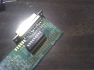
The lowest cost option for connecting the 4Axis board to your PC parallel port is to just take an existing, good quality parallel printer cable and cut off the printer end, then ohm out the wires to find the Data D0-7 signals (pins 3-9 on the PC connector) and strip/solder those wires directly into the 4Axis PCB. Of course, It's a lot quicker to solder on a DB-25 connector and use a parallel extension cable.This connector MUST be a female connector. The cable used from the PC parallel port should be a straight through, male to male.
The DB 25 connector is pressed onto the edge of the PCB. It is positioned starting from the corner of the PCB. The additional pads at the other end are for an optional 36 pins Centronics connector which proved to be very hard to source and expensive. The BB25 does not connect all the useful PC parallel port signals, but it does connect D0-7, and nStrobe (which are outputs from the PC) and nAck, Busy, PError, and Select (which are inputs to the PC).
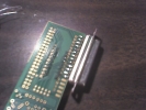
Be sure that the pins aline with the pads (it will only align one way) and then work one end on, and slowly rock back and forth to spread the rest of the pins until the PCB edge is fully pressed against the plastic of the connector. Check the pins for alignment to the pads, both top and bottom and re-position as necessary.
Solder each pin, with the iron touching the end of the pin and the pad and the solder fed from the side, near the body of the connector.
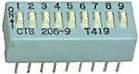
Mode Select Switch and Resistor Network (note that the Linistepper Version 2 already includes a mode switch for everything EXCEPT the high/low power mode)
For Linistepper Version 2, SLAm Stepper or other PMinMO compatible controller boards: The mode switches have been move to the driver on the Linistepper Version 2, and SLAm Stepper boards to be compatible with PMinMO standards so they aren't needed on the 4 Axis board, except for the high/low power setting. You can simply jumper the power setting to ground, or jumper it to an unused pin on the parallel port if you wish to control power from your CNC software. Or install the mode switch as shown in the next section and simply don't use the microstepping mode switches.
High/Low Power jumpered to ground
for constant high power operation on
a PMinMO compatible driver.
High/Low Power for X, Y and A/Z axis jumpered to nStrobe pin on
parallel port for power control by CNC software.Note that R3 has been replaced by a single 1K pullup resistor to the XP pin.
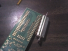
For Linistepper Version 1 boards: Insert the 9 position DIP switch (or 4 position combined with 5 position DIP switches) and solder each pin. It helps to "tack" one pin on each corner while holding the part in as it can easily slip out unexpectedly.
Usually, the kits will have a single, 10 pin (9 resistor) network. If so, insert it with the marked pin in the square pad by the R3 designator and solder each pin.
The kit may, instead, have a combination of a 5 pin, 4 resistor network and another 6 pin, 5 resistor network. Insert both, but ensure the marked pin on each is as far away as possible from the other resistor. The marked pins should go in the holes marked with the arrows in the picture below.
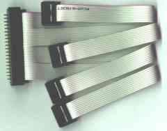
There are any number of ways to cable from the 4 axis board to the Linistepper, SLAm or other controllers. The easiest is to purchase the 4 axis cable:
4 Axis Cable:
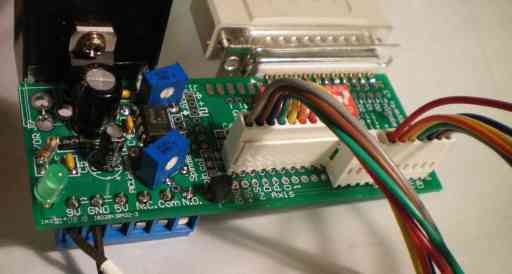
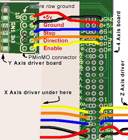
But any method that connects the power, ground, step, direction, and enable lines will do the job. Here is a diagram that shows the basics. In this picture, parts of the 4Axis board and the driver board have been masked out to simplify the presentation. Only the Y Axis driver is shown, the others are connected in the same way.
Simple Direct Wiring: The most basic cable can be made by simply soldering wires between the boards; however, being able to easily remove a driver board for repair or replacement may be worth extra effort. The Linisteppers are pretty solid, but they CAN be destroyed and having a spare to keep your machine up is cost effective. The control and +5 power requirements are minimal so just about any wire can manage the load. Cable length may be an issue with high speed stepping so no more than a foot or 10cm is recommended.
Multiple 8, 9 or 10 pin (or 4 pin in sets of 2) 22 AWG cables with snap lock header. These are simple, effective, but more costly options for connecting the linistepper controllers separately to the 4 Axis board.
Use the snap-lock header supplied with the cable on the 4 Axis board and solder wire end of the cable to the appropriate holes on the Linistepper. Another row of holes has been added so that the snap-lock headers can all be installed on the top of the board, as long as the outside rows are used and the middle row left empty. On the Version 2 Linistepper, watch the pin order, the +5 and Gound connections are swapped.
Notice that the order of the pins on the 4 Axis board is the same for each axis, but run in different directions for the "A" and "Y" axis than they do for the "X" and "A". "X" starts at the upper left of the picture below and runs to the right, as does the "Z" axis below it. The "A" axis is "upside down" in the upper right corner of the picture and runs to the left as does the "Y" axis below it. The labels for the mode switch and a much needed via interfere with some of the labels, but they are just the same as the pins on the axis below them.
So, from the far upper left corner of the picture above, the X Axis signals from left to right are: Ground, Power, Step, Direction, LowPower, Mode 0 and Mode 1. Note that on the V2 Linistepper, the (non) matching connections are Power, Ground, Step, Direction, and LowPower. Mode is selected on the Linistepper V2, not on the 4Axis board. The Y Axis starts from the bottom right, in the same order, but running from right to left. Z is just below X in the same order as X, left to right, and the "A" axis is in the upper right, from right to left.
Micro terminal blocks are also an option for most of the signals.
This makes a pretty good Break Out Board or B.O.B. for general stepper use.
It doesn't include buffer chips, of course, but it brings out the 8 standard
data pins from the parallel port which will generally work fine without a
buffer. One row is installed on top of the board in the holes nearest the
edge, and the other is on the bottom, in the holes closest to the DB25 connector
for the PC parallel cable.
The inner row (on the top, farthest from the edge) is:
GND, XStep (D0), XPower, XMode1, XMode0, XDir (D1), AStep (D6), AMode0, ADir
(D7), and +5. (AMod1 and APower are not accessable).
The outer row (bottom, nearest the edge) is:
GND, ZStep (D4), ZPower, ZMode1, ZDir (D5), YStep (D2), YMode1, YMode0, YDir
(D3), and +5. (ZMod0 and YPower are not accessable).
Here is a PDF you can print, cut and glue to lable the terminals:
boblable.pdf
The two +5 and GND pins can be re-used for two axis each. This assumes you
use 2 blocks of 3 pin terminals and 2 blocks of 2 pins for a total of 10
pins. If you use 3 blocks of 3 pins each, the +5 power lines must all be
run to the terminal block on the +5 Power kit which is a tight fit. Since
we don't stock the 2 pin micro terminal blocks you might as well order them
directly. Jameco has them at a reasonable price:
2081203^
is the 3 pin and
189676^
is the 2 pin
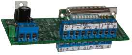
 The Power kit provides regulated +5V supply for
the Linistepper controllers internal use from an unregulated DC power source
such as the motor power supply. Assembly is easy:
The Power kit provides regulated +5V supply for
the Linistepper controllers internal use from an unregulated DC power source
such as the motor power supply. Assembly is easy:
Mount the diode first. The black band goes in the hole farthest from the edge of the PCB.
Ensure the power regulator is in as shown on the solder mask; with the back to the outside of the PCB.
Be sure to mount the capacitors with the longer lead in the hole closest to the "+" outside the circle. The little 100nf is probably not needed, unless the 555 circuit is also being populated; even then, it's relatively unnecessary.
The long lead of the LED needs to be in the hole toward the resistor. The resistor is installed upright; with one lead straight down through one hole and the other bent around and back down through the other hole. The board is marked for a 470 Ohm resistor, but the kit is supplied with a 330 Ohm resistor because it works fine and makes the LED a little easier to see.
The PCB has a place for an AC adapter plug (J2), but it is supplied with the screw terminals for 9V Ground and +5V (opposite side of the PCB from J2) instead. In order to bypass the plug, the pad nearest the corner must be jumpered to the plug pad that connects to D1. This is shown on the figure under the text "shunt."
The 555 kits provides a test pulse for the step line so that you can verify operation of the linisteppers without having a computer hooked up. It can also be used in applications where only simple rotation is needed, such as telescope drives, display rotation, or short event timing. Please note that 555 timers are not terribly accurate time sources over the long term.
The 555 components must be placed and soldered before the relay if you are building both.
The leads on the 555 chip will probably need to be aligned with the holes by pressing the rows together or spreading them apart a little. Probably the easiest method is to insert one row a bit into the holes on that side and then use a fingernail or other semi flat object to press the second row down until those pins also go into their holes. The 555 chip is pretty hardy, but it would be best to solder alternate pins to prevent heat damage and to limit the amount of static electricity by grounding yourself regularly.
Install these either way, they are not polarity sensitive.
The two small variable resistors supplied with the kit may need to have their leads reformed before they will fit in the holes on the board. Finding a reliable source of low cost trim pots with square or round leads is difficult and providing multiple holes allows us to use several different foot prints.R1 controls the duty cycle by adjusting the "on" time and R2 (on the side opposite the DB25/Parallel cable or LM7805 power regulator) controls the frequency by adjusting both the on and off times.
The output of the 555 is connected to the X Axis step signal going out to the stepper driver by resistor R9. We used a resistor there just in case both the parallel port and the 555 were connected at the same time; with the resistor, the parallel port shouldn't be harmed. The value of R9 depends on how much drive your controller needs... if you find it isn't getting the signal, try a smaller resistor or just short it if you are not connecting to a parallel port.
It would be silly and dangerous to put a spindle motor control relay with 120 volts AC power running through it on a hobby circuit board like this. I decided to include the pads for my own personal use since my spindle motor runs on 5 volts DC. I would NEVER recommend that you or anyone else build this part of the circuit for switching high power, high voltage loads.
I installed the coil kick-back suppression diode, D5, on the bottom of the PCB just under R2 (part of the 555 option) with the band towards the power supply end of the PCB and away from the mode switches.
I was careful to install the relay until after soldering down all the 555 components as it sits on the back of the board opposite them and would completely prevent soldering them if it were installed first.
The drive transistor is marked incorrectly. It needed to be installed from the top or in such a way that the emitter is connected to the ground plane, the base is in the middle and the collector runs over to the coil lead, but the silk screen is wrong. When I installed it on the bottom, the circuit didn't work at all, but once I realized the error and installed it on the top of the board, it started working just fine.
The terminal blocks I used are PCB mount miniatures on 0.2" centers. I soldered them to the bottom of the board so that I could still read the lables on the top of the board while hooking up my low power spindle motor leads. I ran the incomming spindle motor supply voltage to the "Comm" terminal and wired from the "N.O." terminal to one side of the spindle motor; the other side of the spindle motor connects to the other side of the spindle motor supply voltage.
Even though my spindle motor is a very low voltage, very safe motor, I clipped off, sanded down and covered all the traces on the PCB that were carrying spindle motor voltage with epoxy and electrical tape so that there was no way I would ever touch the live wire. I also taped over the top of the terminal. Note the set of 4 though holes in the "N.O." which allow the board to be used to make a portable Linistepper test jig. I was very careful to plug and cover BOTH sides of those holes.
There are a number of other things you can do with the 4 axis board. For example:
 External switch port and pullup: Add limit
switches including pull up resistors to sense the home point or excessive
carriage travel. There is space on the bottom of the PCB to solder down 0805
surface mount resistors, starting with "R5", to pull up most of the standard
input pins on a parallel port and there are holes for those pins to be connected
to switches. Notice that the labels for the PC port pins are shifted to the
side to clear the switch ground holes. For example, the nAck connection is
NOT the pad directly to the left of the label nAck in the picture below,
it is the next pad to the left.
External switch port and pullup: Add limit
switches including pull up resistors to sense the home point or excessive
carriage travel. There is space on the bottom of the PCB to solder down 0805
surface mount resistors, starting with "R5", to pull up most of the standard
input pins on a parallel port and there are holes for those pins to be connected
to switches. Notice that the labels for the PC port pins are shifted to the
side to clear the switch ground holes. For example, the nAck connection is
NOT the pad directly to the left of the label nAck in the picture below,
it is the next pad to the left.
 Pads have been provided for 0805 sized
surface mount components to provide this circuit for the X, Y and Z axis.
This picture shows the pads for D4, C6 and R11 on the top side near the X
axis connector. Carefully check the polarity of the diodes when installing
them; they are not always marked correctly on the PCB. The anode of D4 should
be to the left, connected to the X axis Step signal and the cathode connected
to C6, R11, and the X Low Power mode line. Note that closing the low power
mode switch will short the X Step signal through the diode and quite possibly
burn out your PC parallel port. If you choose to try this circuit, it is
strongly recommended that you cut the trace X Low Power trace betwen R3 and
S1 as shown with the red X in the picture. The same concerns apply to the
other two auto low power circuits which are on the bottom of the PCB.
Pads have been provided for 0805 sized
surface mount components to provide this circuit for the X, Y and Z axis.
This picture shows the pads for D4, C6 and R11 on the top side near the X
axis connector. Carefully check the polarity of the diodes when installing
them; they are not always marked correctly on the PCB. The anode of D4 should
be to the left, connected to the X axis Step signal and the cathode connected
to C6, R11, and the X Low Power mode line. Note that closing the low power
mode switch will short the X Step signal through the diode and quite possibly
burn out your PC parallel port. If you choose to try this circuit, it is
strongly recommended that you cut the trace X Low Power trace betwen R3 and
S1 as shown with the red X in the picture. The same concerns apply to the
other two auto low power circuits which are on the bottom of the PCB.See also:
PS2 internal cable? Cut off the end? Berg type connector? SIP header cable?
Kurt R Arnlund of kurta Says:
It should be mentioned that you should use a female DB 25 connector and a straight through male to male DB 25 parallel cable. This is very important because if you use a DB 25 male to female cable and a male DB 25 connector on the "4 axis / 555" board you will wind up with all the connections reversed right to left and it won't work.+
| file: /Techref/io/stepper/linistep/4axis3build.htm, 31KB, , updated: 2013/5/15 17:18, local time: 2025/10/28 05:04,
216.73.216.22,10-3-83-201:LOG IN
|
| ©2025 These pages are served without commercial sponsorship. (No popup ads, etc...).Bandwidth abuse increases hosting cost forcing sponsorship or shutdown. This server aggressively defends against automated copying for any reason including offline viewing, duplication, etc... Please respect this requirement and DO NOT RIP THIS SITE. Questions? <A HREF="http://www.piclist.com/techref/io/stepper/linistep/4axis3build.htm"> Linistepper "4 AXIS / 555 / PWR" kit</A> |
| Did you find what you needed? |
|
o List host: MIT, Site host massmind.org, Top posters @none found - Page Editors: James Newton, David Cary, and YOU! * Roman Black of Black Robotics donates from sales of Linistep stepper controller kits. * Ashley Roll of Digital Nemesis donates from sales of RCL-1 RS232 to TTL converters. * Monthly Subscribers: Gregg Rew. on-going support is MOST appreciated! * Contributors: Richard Seriani, Sr. |
Welcome to www.piclist.com! |
.
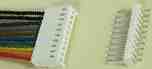 Multiple cables with snap lock headers: