Parts explanation
of Ultrasonic Range Meter
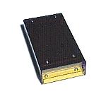 I made the case with the acrylic board. I made the color of the cover purple for the display of the LED to be easy to see. I used the transparent yellow acrylic board in the part of the bottom for the inside be able to be seen. You can jump to the page of making of the case when you click the photograph on the left. 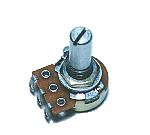 The propagation speed of the sound wave changes with the temperature. This variable resistor is used to revise the error of the display by the change of the temperature. 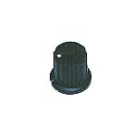 This is the knob to have put to the variable resistor for the temperature revision. I used the small one. 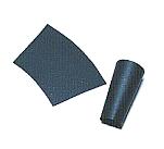 I put the sound horn with the 5-cm length to make the ultrasonic have the directivity. This horn is put for the decrease of the ultrasonic which was reflected at the thing except the measurement object and for the prevention from transmission pulse's entering the receiver sensor. I rolled up and made the paper. The color is OK as well as the black, too. I put the horn, making a hole in the front panel using the reamer. Let out the tip of the horn about 5 mm from the front panel. 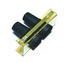  I put the panel which wrote the name at the back. It is the one which was printed in the color to the OHP sheet. I put in the white paper for the letter be able to be clearly seen. 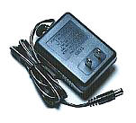 This is the power supply adapter to get DC +12V from AC 100V. The 300-mA electric current can be passed. Because the circuit this time is less than 100 mA, it is enough. It is the cheap one. So, I think that the inner circuit is composed of the small transformer, the rectifier and the simple ripple filter circuit. The one that I resolved before became like this. The output voltage in case of the no-load was to +15V be. At the expensive adapter, the switching regulator is used for the circuit inside. The output voltage of this type is stable. 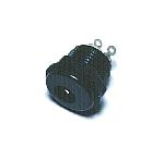 This is the connector to connect the AC adapter. There are some sizes in the plug of the AC adapter. The size of the connector and the plug must be fit. When there is not a connector which fitted the plug, cut off the plug and change into the plug which fitted the connector. The connection of the power supply must be careful so as not to make a mistake in the polarity with the voltage. 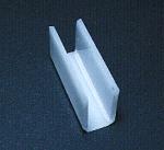 The LED for the distance display is mounted on the printed board. However, I put the mount to have made with the acrylic board to the printed board for the LED to be easy to see from the top of the case and mount the LED onto it. Of course, the lead wires of the LED are short. I soldered to the printed board using the tin plating wire of 0.32 mm. I put on the Teflon pipe of 1 mm in the tin plating wire to prevent from lead wire's touching. Generally, because they don't touch, the Teflon pipes are unnecessary. The acrylic mount was put to the printed board using the glue. 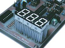 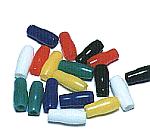 This is the cover which protects the connection part of the wiring. Because the connection part is the circuit inside, it isn't touched. I used because I looked pleasant. 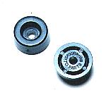 This is the leg to have put to the part in the bottom. When measuring, you have the measurement equipment with the hand and use it. These legs are to protect the case when putting the measurement equipment.  The bench mark point of the range meter is the diaphragm of the ultrasonic sensor. Because the sensor is housed in the case, it is difficult to confirm from outside. Therefore, I pictured the bench mark line on the top of the case. I put the ditch with the acrylic cutter and I painted the fluorescence paint. |