Parts explanation
of the ultraviolet ray exposure equipment (2)
I make the explanation the following about each part of the ultraviolet ray exposure equipment.
[Menu]>[Manufacturing of Original PCB]>[Implement of the PBC making]>[Ultraviolet ray exposure equipment]>[Equipment explanation]
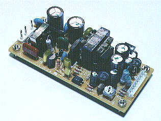
This is the power unit of the timer circuit.
This power unit inputs AC 100 V and outputs DC +5 V and +12 V.
Because it is the switching power supply, it isn't using the large-sized transformer. You aren't too much worried with the mounting space.
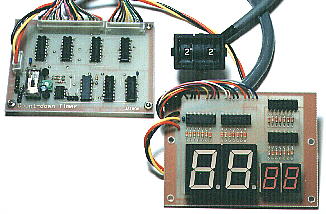
This is the count-down timer to understand the remainder time of the exposure.
I was using the timer circuit which used NE555 in the early stages. Because the time of the exposure is the about 20 minutes, I wait while I am irritated until the exposure ends.
I am using the pattern of the double sided printed board. The setting of the time can be set from the 1 minute to the 99 minutes with the thumbwheel switch.
In the remainder time of the exposure, it is displayed in the digital by the LED in the 7 segments. It displays the minute by the big figure and it displays the second by the small figure. Because the display is the count-down method, you understand the remainder time of the exposure immediately.
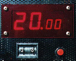
I used the thumbwheel switch for the setting of the time. You can change the setup time by turning the control with the finger. As for the setting, only the minute can be set.
When the timer stops, the setup time is displayed in the LED.
The red button is the start switch (Non lock). The timer begins the count-down when pushing once.
While the timer works, there is not an influence in the count-down even if you change the setup time with the thumbwheel switch. The setting becomes effective when the timer stops.
Also, while the timer works, there is not an influence in the count-down even if you push the start button.
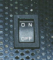
This is the switch of the AC power supply.
When not making this switch ON, the fluorescence light doesn't light up.
As for making this switch ON only, the fluorescence light doesn't light up. The fluorescence light lights up by pushing the start button.
When making this switch OFF, the fluorescence light goes out and the timer circuit becomes the initial state.
When wanting to stop the exposure of the printed board on the way, you make this switch OFF.