I made the timer which is downed in the count until it becomes the 0 seconds from the set time from the 1 minute to the 99 minutes. It is like the kitchen timer. It is bigger than the kitchen timer.
I made this timer with the purpose to use for the ultraviolet ray exposure equipment that is use when making the printed board.
To make the printed board mask, it is necessary to expose the ultraviolet rays in the about 20 minutes. So far, the exposure made stop automatically with the timer which used NE555. In case of being this way, because I didn't understand the time of the remainder, I must wait while I was irritated. Therefore, the remainder time made understand in the digital. It is possible to apply to the other equipment, too.
I made the count-down timer which used PIC16F84A, too. Refer to "Count-down timer".
I assumed the following function to make the circuit. (Specification)
 | It uses the subtraction method for the timer. |
| The subtraction is begun (the timer start) with the non lock switch. |
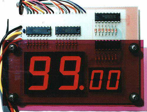
| It displays the remainder time in the digital. |
|
While the timer works, it outputs the a-contact.
(The voltageless contact becomes ON) |
| It stops the operation if becoming with 0'0". |
| It is possible to do the setting in the minute unit from the 1 minute to the 99 minutes. |
| The set value can be confirmed in the setting. |
| It doesn't influence the subtraction even if the set value is changed while the timer is working. |
| It doesn't influence the subtraction even if the start switch is pushed once again while the timer is working. |
|
When setting in the 0 minutes, it doesn't subtract.
(The timer doesn't work) |
|
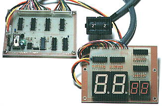
The power supply is +12 V and +5 V.
There is a circuit which changes from +12 V to +5 V, too. In the making this time, it is inputting +12 V and +5 V separately. The pattern drawing has the circuit. This time, it doesn't mount the parts. |
To avoid part's increasing after making the circuit, I omitted the following function.
Because these function lacks didn't influence the use, I was judged not to have to increase the parts.
 | There is not a stop switch. |
|  | It is OK if switching off the power supply. |
When designing the circuit, I assembled the partial shack circuit for the confirmation of the circuit operation and to decide the resistance value.
 | The 10th (the 6 binary counters) operation of the second display |
|
|
The 10th of the second display is the display from 0 to 5.
The IC which was used this time displays the ordinariness from 0 to 9.
It is making display 5 with the NAND gate circuit after the 0 displays.
Does this work as the assumption?
Result : It worked. |
| The resistance value and the capacitor value which makes the oscillation frequency of NE555 1-Hz |
|
|
The frequency becomes 1 Hz in 6.6k-ohm in total value of R4 and VR1 when making C3=100µF, R3=1.2k-ohm in the calculation.
In the measurement, it was as follows. (R4=4.7k-ohm¤VR1=2k-ohm)
| VR1=0-ohm | : | 69 pulses in the 1 minute = 1.15Hz |
| VR1=2k-ohm | : | 52 pulses in the 1 minute = 0.87Hz |
It is possible to make do the 1-Hz oscillation if adjusting VR1. |
| The brightness of the LED |
|
|
I used the one with the different size about the LED for the minute display and the LED for the second display.
The brightness depends on the kind of the LED even if it passes the same electric current. Actually, I make the LED be luminous. Then, I select the resistance value for the brightness to become similar.
It isn't possible to calculate. |
 |