Parts explanation of Digital Clock
 This is the one-chip central processing unit to take charge of the brain of the clock. The feature of the clock is realized by the software which was programed in this PIC. An advanced feature isn't used. As the feature, PIC16F84 is possible. However, I am using PIC16F873 in the relation of the number of the input-output ports.  This is the logic device which it is possible to program. This can attempt to compact-ize a circuit. This time, SR-FF, 3-8 decoder and 1/200000 frequency divider are incorporated into this device. For the details, refer to "Peripheral circuit for Digital Clock". When not using CPLD, the similar circuit can be composed using one 74HC00 for SR-FF, one 74HC138 for 3-8 decode and three 74HC390 for 1/200000 divider.  This is melody IC. 8 pieces of music are memorized in this IC. IC is designed to be able to connect the transistor to drive a speaker. The circuit this time is using amplifier (LM386) outside because for expanding a volume range.
The outline specification of SVM7975C is shown below.
 This is the small amplifier which is possible to let out an about 500-mW output power. It is convenient because it doesn't need a related part. This is used for the amplification of the time signal(Electronic music) and the amplification of the television sound in adjustment.  This is the 3 terminal regulator to get stable +5V. This is used for the power of the LED for the display. It is a 100-mA type.  This is the 3 terminal regulator to get stable +9V. The maximum voltage of LM386N-1 is 12V. So, a regulator is used because it makes not exceed this. It is a 100-mA type.  The stable 12V voltage as the power of the TV tuner with this regulator is made. The TV tuner which was used this time needs the power which was stable because it chose a broadcasting station by the voltage. It is a 100-mA type.  This is the 3 terminal regulator to get stable +5V. This power is used for PIC, CPLD and melody IC. These devices can operate even if commercial power stops because they are backed up by the battery. Because I made the voltage of the battery 7.2 V, few voltage drop type is used for a regulator. The outline specification of S813-50HG is shown below.
 This transistor is used to control the 7 segment LED in the lighting-up. It uses the PNP type because it controls the anode side of the LED. 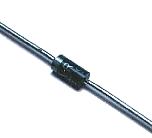 This is a diode for the current control for backup battery. 1A type is used. 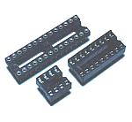 These are IC sockets for mounting PIC, melody IC and low-frequency amplifier. 28 pin socket for PIC is a slim type. If the pin interval suits, it is to be OK even if it uses the one of 14 pins in series. 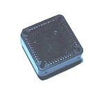 This is the IC socket to mount CPLD. It is a 44 pin type. As for the pin arrangement, refer to "PLCC socket". 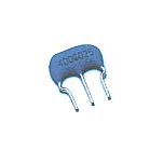 4MHz resonator is used for the clock vibrator of PIC. When changing a frequency, the timing with LED display period and so on change. It isn't related with the precision of the clock. 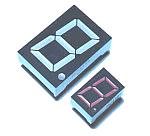 A biggish 7 segment LED is used for time and a minute display. A small type is used for the second display. 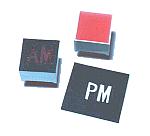 These are the LEDs to use to display the character of AM and PM. Four LEDs are housed inside. The black papers which cut out AM and PM character are pasted on the surface of the LEDs. 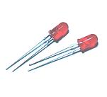 These are the LEDs which are used for the border of the time display and the minute display. 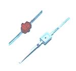 These are the LEDs for power voltage control and input voltage control of melody IC. The maximum voltage of SVN7975C is about 3V. About 2V is made with resistor and LED from the 5V. This LED always lights up. The whiter LED is it and lights up to the green. Because the control signal from PIC is 5 V too, so, a resistor and an LED are similarly used. The red LED is it. 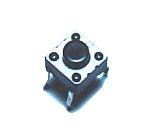 When the power of the clock stops fully, it upsets in the order of the melody. The music can be switched every time it pushes this switch. 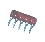 This resistor is used for input pull up of SR-FF. Resistance network is used in the relation of the mounting space.  This resistor is used to choose a TV station. 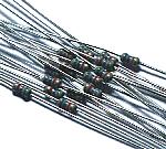 1/8-W resistor is used. 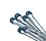 These capacitors are used to bypass the high frequency noise of the input and output of the power supply. 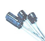 These capacitors are used as the coupling capacitor of the melody IC circuit. Because there is polarity, when mounting, an attention is needed. 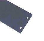 A purple colored acrylic board is put to the front of the LED. The LEDs which light up can be seen cleary with this acrylic board . 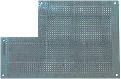 An universal printed board with 40 x 50 halls is used. The board to have cut in the needed size is used. 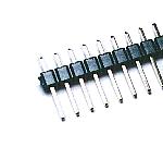 This terminal is used to wire in the part outside. 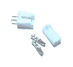 This is the connector which is used for the connection of the speaker. A speaker is put to the front of the case. When repairing and so on, it sometimes removes a wire. Therefore, a connector is used for the connection. 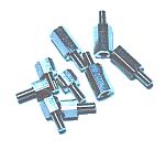 These studs are used for the installation of the printed board, the installation of the acrylic board for the LED filter. For the printed board installation, 5mm is used and for the acrylic board installation, 10mm is used. |
|||||||||||||||||||||||||||||||||||||||||||||||||||||||||||||||||||||||||||||||||||||||||||||||||||||||||||||||||||||||||||||||||||||||||||||||||||||||