 Selecting parts Selecting parts
To make the mask pattern of the printed board, the schematic must be drawn. The part which is used with the schematic is chosen from the one which is registered on the library.The part data which is necessary to draw a pattern as the schematic symbol, the shape, the pin arrangement of the part, and so on, is contained on the library. When the part to want to use isn't registered on the library, it is necessary to look for the similar part or make them. In the case, the part selection work is troublesome. All parts which were used this time are picked out from the standard library.
 Part addition window Part addition window

To add a part to the schematic, click the "ADD" button which is put on the left side in the schematic window.
By this operation, the following part addition window is displayed.
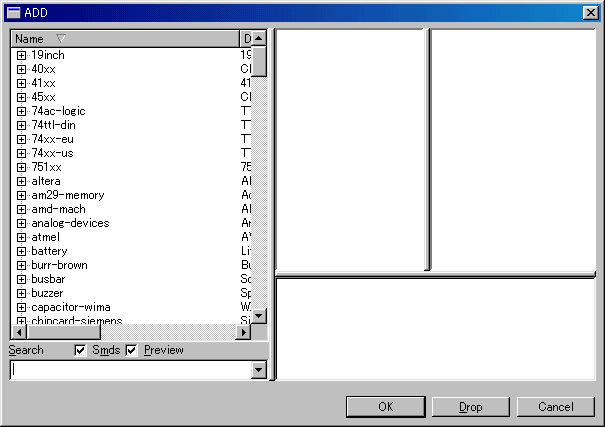
The name which is displayed in the Name column is the contents which are registered on the library. The part data which is made a green mark with the control panel is displayed.
 Addition of the inverter Addition of the inverter
There is no order to chose the part. This time, I put inverter (7404) to the schematic first. It clicks "+" mark of 74xx-us and it develops part list and it selects 74LS04N from 74*04 group.
This part is selected when pushing the "OK" button. Don't push "Drop". When pushing the "Drop" button, this part is deleted from the list. When having pushed the "Drop" button by mistake, it opens "Libraries" of the control panel, and it clicks the part to have dropped on the right and it makes it "Use".
When pushing the OK button, a part is displayed on the schematic. In this condition, the part moves with the movement of the mouse. It pushes the left button of the mouse in the position which puts a part. The position of the part can be changed later, so, it doesn't need serious.
The part can be put continuously. When placing one, it becomes the mode to put next part. In case of more than one element is included in one part like 74LS04, when finishing putting all elements, it is moved to 2nd 74LS04.
Six inverters are housed in 74LS04. This time, two elements are used. However, I put all six to the schematic. The element of the part is selected from the young number. So, when the pin to use is decided, to delete an unnecessary part from later is simpler.
 Stop of the part addition function Stop of the part addition function
 To stop the addition function of the part, it pushes an ESC key or it pushes the "Cancel" button in the schematic window. To stop the addition function of the part, it pushes an ESC key or it pushes the "Cancel" button in the schematic window.
In case of the ESC key, the part addition window appears again and can select the other part immediately.
 Display adjustment of the screen Display adjustment of the screen
In case of the part display of the schematic is small, when clicking the "Fit" button, it is possible to make a circuit fit a window. It is possible to do the expansion or the reduction of the display by "In" or "Out" button which is put neighborhood.
 Delete the parts Delete the parts
 The part which was drawn on the schematic can be deleted by the "Delete" button. The part which was drawn on the schematic can be deleted by the "Delete" button.
This time, IC1D and IC1F are used. After pushing the Delete button, it is deleted when clicking an unnecessary part.
To stop a deletion function, it clicks the Cancel button. 
 Move the parts Move the parts
 When moving the part to have put on the schematic, the "Move" button is used. When moving the part to have put on the schematic, the "Move" button is used.
The part moves with the mouse when clicking a part after pushing the Move button. The part is fix when clicking once again after moving to the position to want to put a part on. To stop a movement function, it clicks the Cancel button. 
 Addition of power and ground terminal Addition of power and ground terminal
 The inverter needs wiring for power and ground. In the addition of the part by the Add button, it is possible to choose the element but it can not choose a power and a ground terminal. The inverter needs wiring for power and ground. In the addition of the part by the Add button, it is possible to choose the element but it can not choose a power and a ground terminal.
The "Invoke" button is used for the addition of the power and the ground terminal. When pushing the Invoke button and clicking an inverter element on the schematic, the use situation of the device is displayed. This table is the list to add the element not to be using with the device.
Because elements D and F are already put on the schematic, it isn't possible to select. P is a power and a ground terminal.
When pushing the OK button, the power and the ground terminal appear on the schematic and it moves with the mouse. The position of this terminal is changed later. This time, I put it on IC1F. It's not need to overlap this terminal and the element. Even if it separates, it doesn't influence pattern creating. To stop an addition function, it clicks the Cancel button. 
 Addition of the other part Addition of the other part
In addition to the inverter, following parts are added to the schematic. As for the method of adding, refer to the example of the inverter.
| Parts | Library | N | Circuit symbol |
| Diode | descrete > DIODE-2,5 | 2 |  |
| The data which has 0.1-inch interval of the lead wire is used to mount a part vertical. |
| Transistor | transistor-small-signal > BC639 | 2 |  |
| The data which has the same position of the lead wire as 2SC1815 with NPN type is used. |
| Resistor | descrete > RESUS-S2,5 | 6 |  |
| The data which has 0.1-inch interval of the lead wire is used to mount a part vertical. |
| Electrolytic Capacitor | descrete > ELC-2,5L | 2 |  |
| The data that a part size was considered is used. |
| LED | led > LED > LED5MM | 2 |  |
| LED data with 5-mm diameter is used. |
| Terminal | wirepad > 2,54/1,1 | 2 |  |
| The terminal data to connect a power is used. |
| +5V | supply1 > +5V | 4 |  |
| The data which shows a +5V power is used. |
| GND | supply2 > GND | 4 |  |
| The data which shows a ground is used. |
| Hole | holes > MOUNT-HOLE > MOUNT-HOLE3.2 | 4 |  |
| The 3.2-mm hole data to install a printed board is used. |
 Arrangement of the part Arrangement of the part
It arranges a chosen part on the schematic. As for the arrangement of each part, it considers wiring.
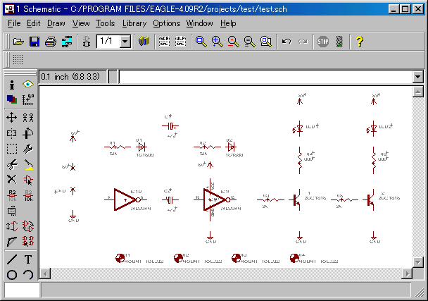 When clicking a screen, you can see an expanded display.
 Rotate the parts Rotate the parts
 When changing the direction of the part, the "Rotate" button is used. After pushing the Rotate button, when clicking the part of the object, the part is made to turn by 90 degrees to the left direction. It turns by 90 degrees every time it clicks. To stop the rotating function, it clicks the Cancel button. When changing the direction of the part, the "Rotate" button is used. After pushing the Rotate button, when clicking the part of the object, the part is made to turn by 90 degrees to the left direction. It turns by 90 degrees every time it clicks. To stop the rotating function, it clicks the Cancel button. 
 Parts value setting Parts value setting
 The "Value" button is used to set the value of the part. It sets a value to the window to set a value and it pushes the OK button. A value is displayed at the part on the schematic. To stop a setting function, it clicks the Cancel button. The "Value" button is used to set the value of the part. It sets a value to the window to set a value and it pushes the OK button. A value is displayed at the part on the schematic. To stop a setting function, it clicks the Cancel button. 
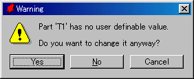
Following warning dialog is displayed when trying to change the value(name) of the transistor.
 |
--------->
Push Yes
and change
the value. |  |
 Parts name setting Parts name setting
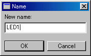
 The "Name" button is used to set the name of the part. It sets a name to the window and it pushes the OK button. A name is displayed at the part on the schematic. To stop a setting function, it clicks the Cancel button. The "Name" button is used to set the name of the part. It sets a name to the window and it pushes the OK button. A name is displayed at the part on the schematic. To stop a setting function, it clicks the Cancel button. 
 |
----------->
OK button |  |
 Change the parts name and value position Change the parts name and value position
 When adding a part, a display position with name and value is fixed. There is possibility that the name or the value overlaps in the complicated circuit. In such a case, it is possible to make a name or a value move to the free position. The button to use for this purpose is the "Smash" button. After pushing the Smash button and starting up Smash feature, it clicks a name or a value. By this, the name and the value have a small + mark. The position with name and value can be moved by pushing the Rotate button or the Move button. To stop this function, it clicks the Cancel button. When adding a part, a display position with name and value is fixed. There is possibility that the name or the value overlaps in the complicated circuit. In such a case, it is possible to make a name or a value move to the free position. The button to use for this purpose is the "Smash" button. After pushing the Smash button and starting up Smash feature, it clicks a name or a value. By this, the name and the value have a small + mark. The position with name and value can be moved by pushing the Rotate button or the Move button. To stop this function, it clicks the Cancel button. 
 |
----------->
By  or or  .
The name or value
can be changed. .
The name or value
can be changed. |  |
 Confirmation of the board Confirmation of the board
I attempt to confirm a board at this point. Because it isn't wiring yet among the parts, it confirms only.
 |
The active window can be changed to the board when pushing the "Board" button on the schematic window. |
 |
When only a white square frame is displayed at the board, it pushes the Fit button.
The white square frame shows a printed board. At this point, the parts are put out of the frame of the printed board. |
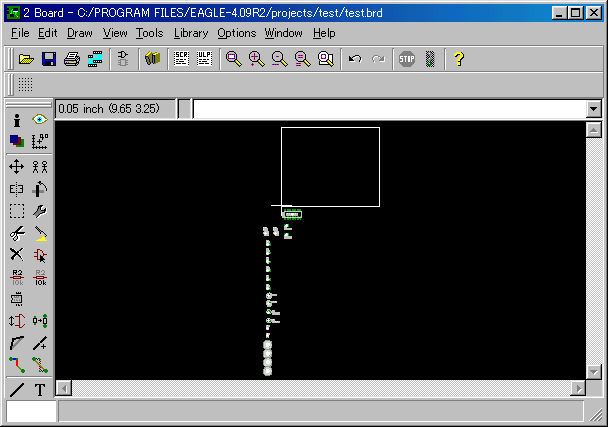 When clicking a screen, you can see an expanded display.
The size of the board which can be created in EAGLE of the freeware is upto 100 x 80 mm. The white frame line shows the size of the board. Even if it changes the position of the line, the size of the board isn't changed. So, the parts can not be put on the place except the white frame which is displayed with the default even if it moves a white line.
|