 Wiring among the parts Wiring among the parts
After putting ending of the part to the schematic, it wires among the parts. EAGLE has the feature of Wire, Net, Bus, Circle, Arc for the wiring among the parts. This time, I wire using the Wire feature.
Usually, Net feature is used in order to change the thickness of a pattern into wiring according to the kind of wiring. Here, I will introduce Wire feature as the method of easiest wiring. As for the wiring by Net feature, please refer to the Width setting of the pattern.
 Wiring using Wire function Wiring using Wire function
 When pushing the "Wire" button, it becomes a mode of the wiring by the Wire function and the wiring among the parts can be drawn. First, when left clicking the lead wire of the part, the starting point of the wiring is set. After that, it double-clicks a mouse at the point which ends wiring. It isn't necessary to keep to push the mouse button during wiring work. When pushing the "Wire" button, it becomes a mode of the wiring by the Wire function and the wiring among the parts can be drawn. First, when left clicking the lead wire of the part, the starting point of the wiring is set. After that, it double-clicks a mouse at the point which ends wiring. It isn't necessary to keep to push the mouse button during wiring work.
To stop this feature, it clicks the Cancel button. 
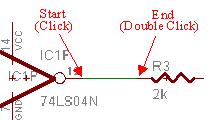 |
It clicks at the start point and it double-clicks at the end point. |
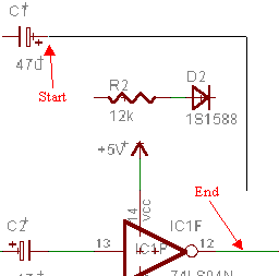 |
In case of the start point and the end point are not on the straight line, when moving a mouse to the end point, the wiring bends being right-angled automatically.
As for the figure on the left, a capture is done on the way of the wiring. So, a connection isn't done to the end point.
The bending position of the wire is controlled by the position of the mouse point. |
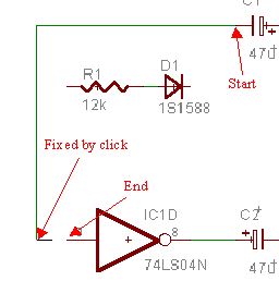 |
In case of the start point and the end point are not on the straight line and should going around the other part, it can be fixed the point by left clicking on the way of the wiring.
In case of EAGLE, when the start point or fixed point and mouse point are not on a straight line, one right-angled corner is made between that point and mouse point. So, if clicking on the way, it is possible to draw the wire which has more than one corner.
Actually, it is possible to understand if drawing.
The drawn line can be erased using the Delete button. |
 Display of the parts information Display of the parts information

When confirming above-mentioned wiring name and so on, the "Info" button is used. The information is displayed when clicking a part or wiring after clicking the Info button. To stop this feature, it clicks the Cancel button. 
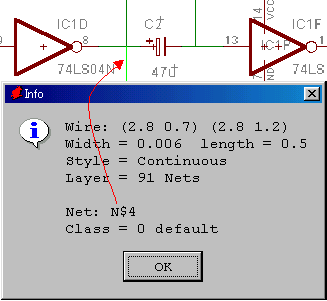 | 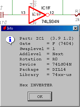 |
 The information of the name of the wiring and so on can be confirmed when clicking wiring. The information of the name of the wiring and so on can be confirmed when clicking wiring. |  The information of the inverter is displayed when clicking an inverter. The information of the inverter is displayed when clicking an inverter. |
 Wiring connection mark Wiring connection mark
 A circular black mark is put to the node of the wiring. This mark doesn't have relation to the wiring of the printed board. It is to confirm the connection of the wire when the person sees a schematic. Especially, in case of the cross connection, it makes a mistake when not putting a mark. A circular black mark is put to the node of the wiring. This mark doesn't have relation to the wiring of the printed board. It is to confirm the connection of the wire when the person sees a schematic. Especially, in case of the cross connection, it makes a mistake when not putting a mark.
When pushing the Junction button, the circular mark which moves with the mouse pointer appears. Because the circle moves along the grid, it fits the node of the wiring. A mark is drawn to the schematic when left clicking at the node. To stop this feature, it clicks the Cancel button. 
 Wiring for the power and the ground Wiring for the power and the ground
This time, I used signal data for the power and the ground. When using these signal data, it isn't necessary to connect a power and a ground with the wire on the schematic. The schematic can be drawn in the simple by these signal data.
 End of schematic drawing End of schematic drawing
The schematic is complete when setting all wiring and connection marks.
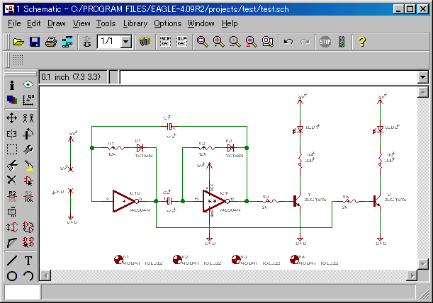 When clicking a screen, you can see an expanded display.
 Electrical Rule Check Electrical Rule Check

After drawing a schematic, it should be confirmed whether or not there is no mistake in the circuit connection. The mistake can be automatically detected by the ERC(Electrical Rule Check) button.
In case of the circuit this time, following message is displayed.
EAGLE Version 4.09r2 Copyright (c) 1988-2002 CadSoft

Electrical Rule Check for C:/PROGRAM FILES/EAGLE-4.09R2/projects/test/test.sch

WARNING: Sheet 1/1: POWER Pin IC1P VCC connected to +5V

Board and schematic are consistent

    0 errors
1 warning |
This is because I made the name of the power as +5V. It is not a mistake.
 Confirmation of the board Confirmation of the board
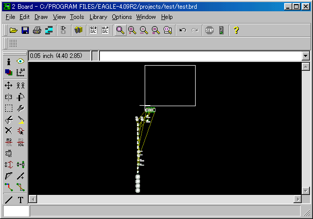
I attempt to confirm a board at this point. Because the connection of each part was ended, the connection of the terminal of each part on the board is done. The yellow line among the parts is the line which shows a connection among the parts. But, these lines are not wiring for the printed board yet.
|
 When pushing the "Wire" button, it becomes a mode of the wiring by the Wire function and the wiring among the parts can be drawn. First, when left clicking the lead wire of the part, the starting point of the wiring is set. After that, it double-clicks a mouse at the point which ends wiring. It isn't necessary to keep to push the mouse button during wiring work.
 A circular black mark is put to the node of the wiring. This mark doesn't have relation to the wiring of the printed board. It is to confirm the connection of the wire when the person sees a schematic. Especially, in case of the cross connection, it makes a mistake when not putting a mark.