Check of operation for Battery charger
|
After confirming that there is no mistake in the wiring, confirm in the operation.
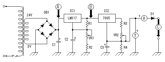
A to C of the following figure shows checkpoints. 
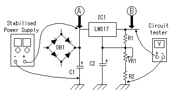
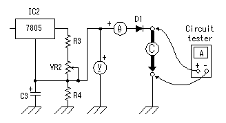
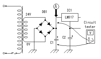
If there should be faulty wiring, there is a possibility of breaking equipment.  Connect the output of stabilised-power-supply to point A, and connect a circuit tester to point B in voltage measurement mode. Connect the output of stabilised-power-supply to point A, and connect a circuit tester to point B in voltage measurement mode.Make VR1 into the minimum voltage side (full of left). Then, raise the voltage of a stabilised-power-supply gradually to 30V. The voltage displayed on a circuit tester should be stabilized in about 8V. If it becomes high more, the voltage control circuit may not be operating normally. Check wiring once again. In my case, when the voltage of 30V was applied from a stabilised-power-supply, the range of 7.9V to 29V has been controlled by changing VR1. This is a value as a design mostly.  Next, operation of a current control circuit is checked. Stop a stabilised-power-supply. Connection of a stabilised-power-supply is still point A. Make a circuit tester into current measurement mode, and connect with the output terminal of a charger. Because the ammeter is attached to the charger, you may short-circuit the plus terminal and minus terminal of an output, without using a circuit tester. Make VR2 into the minimum current side (full of left). Then, raise the voltage of a stabilised-power-supply gradually to 30V. A circuit tester's current should be stabilized in about 85mA. When flowing more, the current control circuit may not be operating normally. Check wiring once again. In my case, when the voltage of 30V was applied from a stabilised-power-supply, it has controlled in 85.6mA to 500mA by changing VR2. This is a value as a design mostly. Even if it changes VR1 for voltage control, current does not change. This is also as a design. The voltmeter of a charger shows about 1 V in this condition. This is the voltage applied to the reverse current prevention diode (about 0.6V), the ammeter of a charger and circuit tester. Because they have some resistance, the voltmeter of a charger is not set to 0V even if it short-circuits an output.  Finally operation of a rectifier circuit is checked. A voltage of RMS (Root Mean Squared) is used for alternating voltage. This voltage is not the maximum of voltage (peak voltage).  Why is RMS used for alternating voltage? Because, calculation of electric power is easy. As for alternating voltage, peak voltage is not held but voltage is changing with time. Therefore, peak voltage cannot be used when calculating electric power (quantity which electricity works). RMS voltage is Because the outputs of the transformer used this time are 24Vrms, peak voltage is about 33.6V. Actually, there was 35.0V voltage at point A. This error is caused by the error of AC input voltage and accuracy of transformer. Normal operation of a rectifier circuit was also checked. If a battery is charged by the 500mA charging current, the portion of the bottom of a charger will get warm. It is not hot. Calculation of the power consumption of IC for voltage control and current control is shown below. The premise of calculation is the following. Charge voltage is 14V. Charging current is 500mA. And voltage of voltage control is 23V.
Conversely, if voltage for voltage control is made low, the power consumption of IC for voltage control will increase, and the power consumption of IC for current control will decrease. Total power consumption seldom changes. Because voltage control is for over charge prevention of a battery, it is the above values generally. As a charger, the power consumption of R3 and VR2 (about 3 W) is added to the above-mentioned value. So, it can be regarded as about 10W power consumption. If the charging current is reduced, power consumption will decrease more. The performance of this equipment is summarized as follows.
The maximum voltage is high from the value previously explained at Check of the voltage control circuit operation.
This is because it applied only to 30V in Check of the voltage control circuit operation. |