Making of a control circuit Making of a control circuit
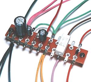 |

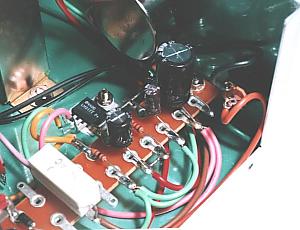
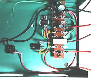
A control circuit is assembled first.
Temporary soldering of the grounding wire is carried out first. This is soldering for preventing movement of a grounding wire. It is made not to plug up the hole of a terminal. It is for letting the lead wire of parts pass in the hole of a terminal.
It solders from small parts. Because the size of an electrolytic capacitor or a cement resistor is large, it is attached later.
After soldering all parts, wirings are soldered to terminals. I used wiring of various colors. When using the wire of the same color, cautions are required to prevent mistakes in wiring. |
|
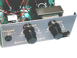
Meter mounting holes
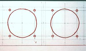
The work which makes the hole for meter is the most serious with this equipment.
Cut somewhat thick paper to the same width as a panel. And draw the position of meter and a mounting screw. |
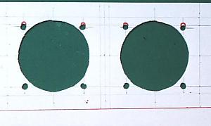
Make the big hole of the center for mounting meter with a cutter knife etc.
Next, mount meter in a hole and check the position of a mounting screw. |
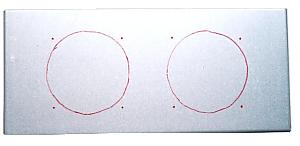
Apply the panel of paper to a case and decide the position in which holes are made. |
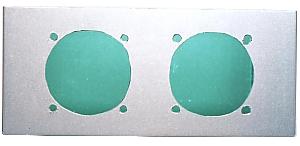
Make the mounting holes of meter in a case.
Because I don't have a jigsaw, I used a thread handsaw. |
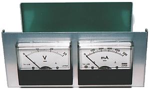
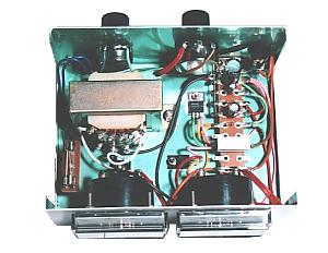
This is the photograph with which meter was mounted. |
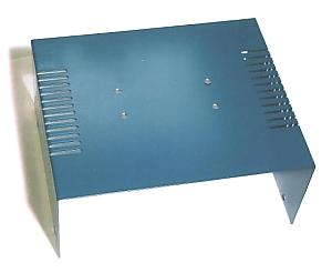
This is the photograph seen from the back side.
Paint of green is carried out to the inside of the case used this time. |
|
Part mounting holes
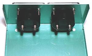
Place parts and decide the position of mounting holes. Confirm that parts do not collide. |
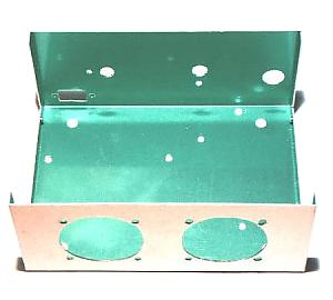
This is the photograph which made the mounting holes of parts. |
|
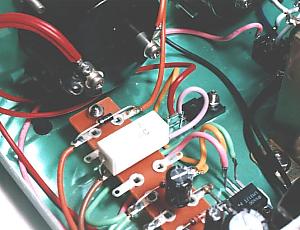
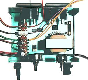
Part mounting and wiring
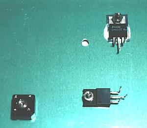
Mount the diode bridge and regulators which are small parts first. An insulated sheet is required when LM317 is mounted. Heat comes out from these parts. Therefore, mount after applying silicone grease so that heat may tend to get across to a case.
If the lead wire of a regulator is bent alternately, it will become easy to do wiring. |
Next, mount a control circuit. When paint is carried out for the inside of a case, the paint of the place which mounts a control circuit needs to be removed with a driver etc.
The wire for small parts should be wired first. |
|
Back panel
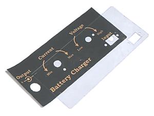
I attached the panel which wrote the name of each part to the back of equipment.
A panel is what was printed on paper and fixed with the transparent acrylics board of 0.5mm thickness. |
This is a picture furnished with a panel.
A crevice is made between an acrylics board and a case. In order to prevent dust going into a crevice, I stucked the Scotch tape on the circumference of a panel. |
|
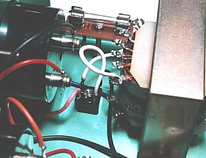
Part mounting holes
The holes for metallic-ornaments attachment are made according to the thickness of the shaft which attaches equipment. |
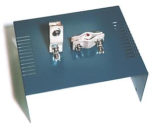
This is a picture furnished with metallic ornaments. |
|
Wiring of each part
|