Stepper motors are devices, which convert electrical impulses into discrete
mechanical rotational movements. In a typical stepper motor, power is applied
to two coils. Two stator cups formed around each of these coils, with pole
pairs mechanically offset by ½ a pole pitch, become alternately
energized North and South magnetic poles. Between the two stator-coil pairs
the offset is ¼ of a pole pitch.
The permanent magnet rotor has the same number of pole pairs as the stator
coil section. Interaction between the rotor and stator (opposite poles attracting
and like poles repelling) causes the rotor to move ¼ of a pole
pitch per winding polarity change.
Motors are available in either 2 coil (bipolar) or 4 coil (unipolar) windings.
In the unipolar version, the coils are bifilar (two side by side wires) wound
on each stator half and opposite ends of each pair are connected together
to form a center tapped coil. With this method, the flux is reversed by powering
either one end or the other of the bifilar coil pair with the center connected
to common. For a bipolar motor, an external device referred to as an H-Bridge
can be used to reverse the polarity of the winding and thus the flux. An
H-Bridge can also drive a unipolar motor by not connecting the center tap
(common) lead or using only one of the windings in the pair.
Unipolar stepper motors require only 4 transistor switches which greatly
simplifies the drive circuitry when compared to the 8 transistors required
to drive a bipolar motor (dual H-Bridges). However, for unipolar stepper
motors to have the same number of turns per winding as a bipolar motor, smaller
diameter must be employed so that both windings may fit in the space of one.
The resistance increases due to the smaller wire diameter. Due to increased
resistance, unipolar stepper motors have 30% less torque at low step rates.
At higher step rates, the torque outputs are approximately the same.
For a stepper motor to take one step a four part switching sequence is involved
which is commonly referred to as Wave Drive.
Sequence |
Coil A |
Coil B |
1 |
+ |
off |
2 |
off |
+ |
3 |
- |
off |
4 |
off |
- |
In the chart above, + indicates the coil is conducting in the forward direction
with one end being positive with respect to ground. The - indicates that
the coil is conducting in the opposite direction. Continuing the sequence
as outlined above causes the rotor to rotate in a forward direction. Reversing
this sequence causes the motor to rotate in the reverse direction. The coils
only are required to be energized long enough for the rotor to move to its'
next position. If the coil remains energized, it will lock the shaft of the
motor and this situation is commonly used for stopping or putting on the
brakes. The torque developed in this manner is referred to as the motor's
holding torque. Operated at a fixed frequency, the electrical input to the
motor appears as a two-phase 90-degree shifted square wave.
The no load or constant load accuracy of a 7.5 degree/step motor is within
0.5% noncumulative. This means that the positioning error is always the same
whether the rotational movement is one step or 1000 steps. Since the step
error is noncumulative, it averages itself out to zero within a 4-step sequence,
which corresponds to 360 electrical degrees. The 4-step sequence uses the
same coil, magnetic polarity and flux path. With this in mind, the most accurate
method of positioning would be obtained by stepping in multiples of 4.
It is also possible to step the motor according to an 8-part sequence to
obtain half steps. For example a motor with a step size of 7.5 degrees/step
could be half stepped to obtain motion of 3.75 degrees/step. Applications
utilizing this method will suffer a lower holding torque on every other half
step since only one winding will be energized. Accuracy will also suffer,
as winding and flux conditions are not similar for each ½ step.
The half step sequence is listed in the chart below.
Sequence |
Coil A |
Coil B |
1 |
+ |
+ |
2 |
+ |
off |
3 |
+ |
- |
4 |
off |
- |
5 |
- |
- |
6 |
- |
off |
7 |
- |
+ |
8 |
off |
+ |
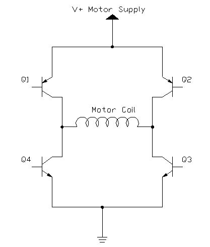
The drawing below depicts a simple H-Bridge. It consists of two pairs of
transistors connected to each end of the motor coil. Q1 and Q2 are connected
to the positive motor supply source. Q3 and Q4 are connected to ground. By
putting a positive voltage on the base of one of the transistors, it will
cause the transistor collector/emitter junction to conduct.
By switching transistors Q1 and Q3 on, it will cause current to flow through
the motor coil in the forward or + direction. By switching Q2 and Q4 on,
it causes current to flow through the motor coil in the reverse or - direction.
The logic controlling which transistors are switched must be quite precise
as switching transistors Q1 and Q4 or Q2 and Q3 on at the same time will
result in shorting the power supply directly to ground which will destroy
the transistor pair and possibly the power supply as well.
Logic must be provided to inhibit any programming error, which would result
in switching the wrong transistors on at the incorrect time. Additionally,
timing circuitry should be employed that the correct transistors are switched
on only after the others are switched off. Simply driving the H-Bridge directly
from a microcontroller would be ill advised. On power-up, the outputs of
many microcontrollers go high momentarily which would instantly destroy an
H-Bridge without the proper inhibit circuitry for disallowed conditions.
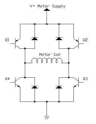
Whenever an inductor is energized, higher than normal current is drawn while
the magnetic field of the coil builds. Conversely, when the inductor is
de-energized, the magnetic field in the coil collapses causing a voltage
to be induced in the inductor and current to flow in the opposite direction.
The reverse current flow may damage the switching transistors in the circuit.
In order to correct the problem with the polarity reversal caused by the falling magnetic field inducing a current in the inductor, snubber diodes are installed. The direction of the diodes is such that during normal operation, the diodes do not conduct. When the falling magnetic field causes reverse current flow, the diodes conduct this current directly to ground and away from the switching transistors. The circuit below depicts a simple H-Bridge with snubber diodes installed.
The Allegro UDN2998 Dual Full Bridge Motor Driver IC handles all of the problems of H-Bridges and incorporates this technology in a single package. Current prices for this chip are less than $7 in single quantities. The UDN2998 features:
3 Amp peak output current
2 Amp continuous current
Output voltage to 50 Volts
Integral output suppression diodes
Output current sensing
TTL / CMOS compatible Inputs
Internal thermal shutdown circuitry
Crossover -Current protection
12 Pin package
Due to the logic circuitry preventing crossover-current protection (switching
on the wrong transistors creating a short circuit) each side of the dual
bridge has an enable and phase input instead of controlling the switching
transistors directly. A truth table is depicted below.
Enable Input |
Phase Input |
Output 1 |
Output 2 |
Low |
High |
High |
Low |
Low |
Low |
Low |
High |
High |
High |
Open |
Low |
High |
Low |
Low |
Open |
Referring back to the Wave Drive table for half stepping our motor and also the UDN2998 truth table, we can make up a logic table depicting the output for our microcontroller. This table is shown below.
Microcontroller Output Table
Sequenced for Half-Stepping
Sequence |
Coil A |
Coil B |
Coil B Enable RA3 |
Coil B Phase RA2 |
Coil A Enable RA1 |
Coil A Phase RA0 |
1 |
High |
High |
0 |
0 |
0 |
1 |
2 |
High |
Off |
1 |
0 |
0 |
1 |
3 |
High |
Low |
0 |
1 |
0 |
1 |
4 |
Off |
Low |
0 |
1 |
1 |
0 |
5 |
Low |
Low |
0 |
1 |
0 |
0 |
6 |
Low |
Off |
1 |
0 |
0 |
0 |
7 |
Low |
High |
0 |
0 |
0 |
0 |
8 |
Off |
High |
0 |
0 |
1 |
0 |
If you compare the half step and full step tables, you will notice that all of the full step sequences appear somewhere in the half step table, but not in the same order. This information is useful in building a look-up table in your program and not having to duplicate the lines of code that would appear in both half step and full step output sequences.
Pin |
Function |
1 |
Ground |
2 |
Phase A |
3 |
Enable A |
4 |
Output 1A |
5 |
Bridge A Supply Common |
6 |
Output 2A |
7 |
Output 2B |
8 |
Bridge B Supply Common |
9 |
Output 1B |
10 |
V+ Motor Supply |
11 |
Enable B |
12 |
Phase B |
You can obtain a complete data sheet at www.allegro.com that provides more
information about temperature, heat sinking and other modes of operation
such as the chopper mode.
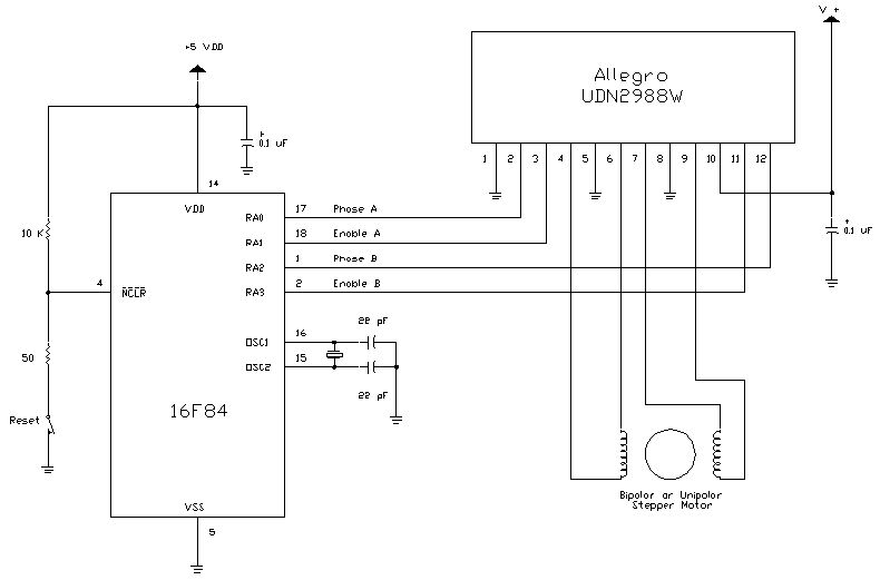
The following schematic diagram shows a circuit, which places what we have
discussed into practice. I am using a 16F84 microcontroller in this example,
however, any microcontroller which is supported by JAL will work. You will
only need to make a few changes in both the circuit and the program to
accommodate the changes.
Power for the circuit comes from one or two external power supplies. Operating
off a single supply is a bit trickier due to the noise generated by the switching
transistors. The 5 volt supply for the microcontroller should be well regulated.
It is very important not to omit the two 0.1 uF capacitors shown and they
should be placed as close as possible to their respective chips. These are
decoupling capacitors and if omitted can cause unreliable operation or the
circuit not to function at all. I experienced lack of function without these
capacitors when operating from the same power supply and even including a
5 volt regulator for the microcontroller.
Power for the motor should be based on the current and torque requirements
for the motor and what kind of load the motor must move. A little experimentation
may be in order to find just the right value for the motor supply voltage.
Increasing the voltage will increase the motor current and the torque produced
while at the same time increasing the heat produced by the UDN2998.
You will notice both a 10 K and a 50 Ohm resistor connected to the reset
lead of the microcontroller. You might be able to omit the 50 Ohm resistor.
The 10 K resistor pulls the reset lead up to the 5 volt supply, without it,
the microcontroller will remain in the reset mode and the circuit will not
operate. The 50 ohm resistor is included as recommended by Microchip Technologies
in order to prevent the reset pin from going negative when the reset switch
is pressed.
The UDN2998 is not the only H-Bridge that is manufactured by Allegro or by
other manufacturers. You might select a different chip based on your project
requirements. Pins 5 and 8 of the UDN2998 are the ground returns for each
side of the H-Bridge. If necessary, you could install current limiting or
current sensing resistors at this point. Beware of the wattage rating of
any resistors installed here as a motor drawing several Amps at even 12 Volts
will require a resistor of considerable wattage to prevent it from burning
up.
Following is the JAL library that you will need to include in your program
to drive a stepper motor using this configuration.
--
-- Program: bipolib.jal library
--
-- Date: 14 July 2000
--
-- Author: G. Shearer
-- Vanderbilt University
-- Nashville, TN
--
-- Purpose: for driving both bipolar and unipolar stepper motors
-- uses Allegro UDN2998 dual H bridge
-- Copyright (C) 2000 G. Shearer
--
-- This library is free software; you can redistribute it and/or
-- modify it under the terms of the GNU Library General Public
-- License as published by the Free Software Foundation; either
-- version 2 of the License, or (at your option) any later version.
--
-- This library is distributed in the hope that it will be useful,
-- but WITHOUT ANY WARRANTY; without even the implied warranty of
-- MERCHANTABILITY or FITNESS FOR A PARTICULAR PURPOSE. See the GNU
-- Library General Public License for more details.
--
-- You should have received a copy of the GNU Library General Public
-- License along with this library; if not, write to the
-- Free Software Foundation, Inc., 59 Temple Place - Suite 330,
-- Boston, MA 02111-1307, USA.
--
procedure stepout ( byte in seq, byte in speed ) is
-- sends seq nibble to output
if seq == 0 then
port_a = 0b_0001
elsif seq == 1 then
port_a = 0b_1001
elsif seq == 2 then
port_a = 0b_0101
elsif seq == 3 then
port_a = 0b_0110
elsif seq == 4 then
port_a = 0b_0100
elsif seq == 5 then
port_a = 0b_1000
elsif seq == 6 then
port_a = 0b_0000
elsif seq == 7 then
port_a = 0b_0010
else
port_a = 0b_1010
end if
delay_1ms( speed )
end procedure
procedure fullforward ( byte in speed ) is
-- makes one full step in the forward direction
stepout( 1, speed )
stepout( 7, speed )
stepout( 5, speed )
stepout( 3, speed )
end procedure
procedure fullreverse ( byte in speed ) is
-- makes one full step in the reverse direction
stepout( 3, speed )
stepout( 5, speed )
stepout( 7, speed )
stepout( 1, speed )
end procedure
procedure halfstep ( bit in direction, byte in out seq, byte in speed ) is
-- makes one half step in the proper direction and remembers which half
step
for 4 loop
if direction == true & seq < 7 then
seq = seq + 1
elsif direction == true & seq == 7 then
seq = 0
elsif direction == false & seq > 0 then
seq = seq - 1
elsif direction == false & seq == 0 then
seq = 7
end if
stepout ( seq, speed )
end loop
end procedure
procedure fullstep ( bit in direction, byte in speed ) is
-- detects forward/reverse direction and calls proper fullstep procedure
if direction == true then fullforward ( speed )
else fullreverse ( speed )
end if
end procedure
I have included a copy of the library file
so you will not need to type the whole thing in yourself. This library contains
a few procedures, but from a program point of view, you will only need to
add the line:
include bipolib
in your program. Every time you wish to have the motor take a full step,
include the following line in your program:
fullstep ( direction, speed )
where direction is either true for forward or false for reverse and speed
is the number of milliseconds between steps.
For half-stepping, you will need to initialize the step sequence at the beginning
of your program. Just add the following line:
var byte seq = 0
which will start half stepping on the first half step. The procedures in
the library will then keep track of which half step to take each time it
is called. Each time you wish to take a half step, use the following line
in your program:
halfstep ( direction, seq, speed )
where direction and speed are exactly the same as for full stepping and seq
is the sequence counter used to keep track of which half step to take.
Here is s quick rundown on each of the procedures contained in bipolib.jal
Procedure fullstep
Determines forward / reverse
Calls either fullforward or fullreverse
Passes speed variable
Procedure halfstep
Determines last sequence
Determines forward / reverse
Increments sequence
Calls stepout
Passes sequence and speed variables
Procedure fullforward
Sets sequence
Calls stepout
Passes sequence and speed variables
Procedure fullreverse
Sets sequence
Calls stepout
Passes sequence and speed variables
Procedure stepout
Looks up binary output based on sequence value
Sets port a
Adds delay based on speed
Following is a demonstration program that utilizes bipolib.jal and exercises
the stepper motor to prove functionality of the circuit and
library.
--
-- Program: biptest.jal
--
-- Date: 13 July 2000
--
-- Author: G. Shearer
-- Vanderbilt University
-- Nashville, TN
--
-- Purpose: Demo program for bipolib.jal
-- ( bipolar stepper motor library)
--
-- Copyright (C) 2000 G. Shearer
--
-- This library is free software; you can redistribute it and/or
-- modify it under the terms of the GNU Library General Public
-- License as published by the Free Software Foundation; either
-- version 2 of the License, or (at your option) any later version.
--
-- This library is distributed in the hope that it will be useful,
-- but WITHOUT ANY WARRANTY; without even the implied warranty of
-- MERCHANTABILITY or FITNESS FOR A PARTICULAR PURPOSE. See the GNU
-- Library General Public License for more details.
--
-- You should have received a copy of the GNU Library General Public
-- License along with this library; if not, write to the
-- Free Software Foundation, Inc., 59 Temple Place - Suite 330,
-- Boston, MA 02111-1307, USA.
--
-- includes
include 16f84_4
include jlib
include bipolib
-- configure ports
port_a_direction = all_output
-- initialize variables
var byte speed = 3
var bit direction = true
var byte seq = 0
-- here da program
forever loop
direction = true
for 100 loop
fullstep ( direction, speed )
end loop
direction = false
for 100 loop
fullstep ( direction, speed )
end loop
direction = true
for 200 loop
halfstep ( direction, seq, speed )
end loop
direction = false
for 200 loop
halfstep ( direction, seq, speed )
end loop
end loop
I believe the demonstration is self-explanatory. I encourage you
to experiment with the demonstration program to get a feel of how it
operates.
I am certain that some typos or omissions have crept into this explanation
so I would be grateful for any corrections to errors you have observed. Please
write to me at g.shearer@vanderbilt.edu
I welcome your comments and would be pleased to learn of any projects you
have done which utilize the information, circuits, library or demonstration
program contained here.
See also:
Questions:
TakeThisOuTsaeedturk at yahoo.com well it was knowledgefull but i don know what is "jal". do someone has c/C++ code and an 74xxx based circuit for bi-directional ctrl form pc port?. I will weight. saeedturk@yahoo.com+
Well, JAL is Just Another Language. Look at Steppers for general information.
Code:
Comments:
| file: /Techref/piclist/jal/drivingbipolarsteppermotors.htm, 40KB, , updated: 2020/6/3 09:55, local time: 2025/10/17 02:54,
216.73.216.114,10-3-244-150:LOG IN
|
| ©2025 These pages are served without commercial sponsorship. (No popup ads, etc...).Bandwidth abuse increases hosting cost forcing sponsorship or shutdown. This server aggressively defends against automated copying for any reason including offline viewing, duplication, etc... Please respect this requirement and DO NOT RIP THIS SITE. Questions? <A HREF="http://www.piclist.com/techref/piclist/jal/drivingbipolarsteppermotors.htm"> Driving Bipolar Stepper Motors</A> |
| Did you find what you needed? |
|
o List host: MIT, Site host massmind.org, Top posters @none found - Page Editors: James Newton, David Cary, and YOU! * Roman Black of Black Robotics donates from sales of Linistep stepper controller kits. * Ashley Roll of Digital Nemesis donates from sales of RCL-1 RS232 to TTL converters. * Monthly Subscribers: Gregg Rew. on-going support is MOST appreciated! * Contributors: Richard Seriani, Sr. |
Welcome to www.piclist.com! |
.