Circuit explanation
of Ultrasonic Range Meter unit
|
I am using two 555 timer ICs for the transmitter circuit of the ultrasonic. As for the operation of the oscillation circuit which used 555, refer to "555 oscillator".  IC1 is the oscillation circuit to control the sending-out time of the ultrasonic pulse. The time of the oscillation pulse can be calculated by the following formula. Actually, with the error of the parts, it is different from the calculation a little. The condition : RA = 9.1M-ohm, RB = 150K-ohm, C = 0.01µF
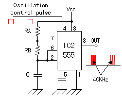 IC2 is the circuit to make oscillate the ultrasonic frequency of 40KHz. IC2 is the circuit to make oscillate the ultrasonic frequency of 40KHz.Oscillation's operation is same as IC1 and makes oscillate at the frequency of about 40 KHz. It makes RB>RA to bring the duty(Ratio of ON/OFF) of the oscillation wave close to 50%. The frequency of the ultrasonic must be adjusted to the resonant frequency of the ultrasonic sensor. Therefore, I am made to be able to adjust the oscillation frequency by making the RB the variable resistor (VR1). The output of IC1 is connected with the reset terminal of IC2 through the inverter. When the reset terminal is the H level, IC2 works in the oscillation. The ultrasonic of 40KHz is sent out for the 1 millisecond and pauses for the 62 milliseconds. The calculation example of the frequency is shown below.
The condition : RA = 1.5K-ohm, RB = 15K-ohm. C = 1000pF
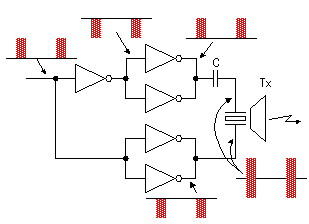 The inverter is used for the drive of the ultrasonic sensor. The two inverters are connected in parallel because of the transmission electric power increase. The phase with the voltage to apply to the positive terminal and the negative terminal of the sensor has been 180 degrees shifted. Because it is cutting the direct current with the capacitor, about twice of voltage of the inverter output are appied to the sensor. 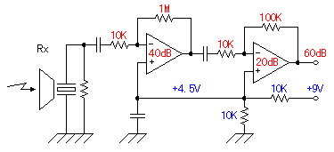 The ultrasonic signal which was received with the reception sensor is amplified by 1000 times(60dB) of voltage with the operational amplifier with two stages. It is 100 times at the first stage (40dB) and 10 times (20dB) at the next stage. The ultrasonic signal which was received with the reception sensor is amplified by 1000 times(60dB) of voltage with the operational amplifier with two stages. It is 100 times at the first stage (40dB) and 10 times (20dB) at the next stage.As for the dB (decibel), refer to "Logarithm Table". Generally, the positive and the negative power supply are used for the operational amplifier. The circuit this time works with the single power supply of +9 V. Therefore, for the positive input of the operational amplifiers, the half of the power supply voltage is appied as the bias voltage and it is made 4.5 V in the central voltage of the amplified alternating current signal. When using the operational amplifier with the negative feedback, the voltage of the positive input terminal and the voltage of the negative input terminal become equal approximately. So, by this bias voltage, the side of the positive and the side of the negative of the alternating current signal can be equally amplified. When not using this bias voltage, the distortion causes the alternating current signal. When the alternating current signal is amplified, this way is used when working the operational amplifier for the 2 power supply with the single power supply. As for the operation of the operational amplifier, refer to "Operation explanation of the triangular wave oscillator". 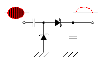 The detection is done to detect the received ultrasonic signal. It is the half-wave rectification circuit which used the Shottky barrier diodes. The DC voltage according to the level of the detection signal is gotten by the capacitor behind the diode. the Shottky barrier diodes are used because the high frequency characteristic is good. As for the Shottky barrier diode, refer to "Diodes". 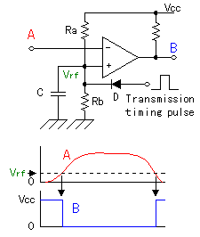 This circuit is the circuit which detects the ultrasonic which returned from the measurement object. The output of the detection circuit is detected using the comparator. At the circuit this time, the operational amplifier of the single power supply is used instead of the comparator. The operational amplifier amplifies and outputs the difference between the positive input and the negative input. This circuit is the circuit which detects the ultrasonic which returned from the measurement object. The output of the detection circuit is detected using the comparator. At the circuit this time, the operational amplifier of the single power supply is used instead of the comparator. The operational amplifier amplifies and outputs the difference between the positive input and the negative input.In case of the operational amplifier which doesn't have the negative feedback, at a little input voltage, the output becomes the saturation state. Generally, the operational amplifier has tens of thousands of times of mu factors. So, when the positive input becomes higher a little than the negative input, the difference is tens of thousands of times amplified and the output becomes the same as the power supply almost.(It is the saturation state) Oppositely, when the positive input becomes lower a little than the negative input, the difference is tens of thousands of times amplified and the output becomes 0 V almost.(It is in the OFF condition) This operation is the same as the operation of the comparator. However, because the inner circuit is different about the comparator and the operational amplifier, the comparator can not be used as the operational amplifier. At the circuit this time, it connects the output of the detection circuit with the negative input of the signal detector and it makes the voltage of the positive input constant.
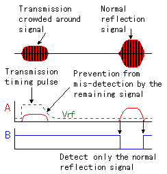 There is another device in this circuit. It is the diode (D) which connects with the side of the positive input. There is another device in this circuit. It is the diode (D) which connects with the side of the positive input.The pulse sending-out timing signal of the transmitter is appied to this diode. So, it makes not detect the transmission signal which was crowded when sending out the ultrasonic signal from the transmitter and going around to the reception sensor, making the voltage of the positive input of the signal detector rise in the pulse sending-out timing signal. The transmission signal has the remaining signal even if it stops the transmission timing pulse. So, it makes the falling of the transmission timing pulse gentle with the capacitor (C) and it is preventing from the mis-detection by the remaining signal. The value of this capacitor is the one point which decides the efficiency of the equipment. The detection start time becomes late when the value of this capacitor is big and can not do the measurement of the short distance. The equipment this time makes the transmission pulse long(About 1 millisecond) to make the measurement possible to the about 10-m distance and makes the capacitor of the detector big a little. Therefore, the shortest measurement distance becomes about 40 cm. To measure the short distance, making TL in IC1 short, the value of the capacitor of the signal detector must be made small. Way, in the time that the ultrasonic goes and returns in the 30-cm distance at 20°C, it is the 1.75 milliseconds. 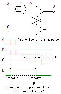 This circuit is the gate circuit to measure the time which is reflected with the measurement object and returns after sending out the ultrasonic. It is using the SR (the set and the reset) flip-flop. For the details of SR-FF, refer to "The operation explanation of the D-type flip-flop". The set condition is the time which begins to let out the ultrasonic with the transmitter. It uses the transmission timing pulse. The reset condition is the time which detected the signal with the signal detector of the receiver circuit. That is, the time that the output of SR-FF (D) is in the ON condition becomes the time which returns after letting out the ultrasonic. 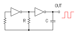 This circuit is the oscillator which makes the pulse to measure the propagation time of the ultrasonic. It is the oscillation circuit which used the CMOS inverter. The oscillation frequency can be calculated by the following formula.
f = 1 / ( 2.2 x C x R )
As for the operation of this oscillator, refer to "Square wave oscillator(2)". The oscillation frequency this time is about 17.2 KHz. This frequency is calculated from the propagation speed (343.5m/sec) of the sound wave at 20°C. As for the difference with the propagation speed of the sound wave by the temperature, refer to "The sound wave propagation speed in the air". For example, in case of the 1-m distance, the time that the sound wave depends on the going and returning is 2m/343.5m/sec = 5.82msec. The frequency to make the 100 pulses occur to at this time becomes the frequency of the measurement pulse. It becomes f = 100/(5.82 x 10-3) = 17.18 x 103 = 17.18KHz Supposing that the capacitor (C) is 2200 pF, the value of the resistor (R) is as follows.
Because the propagation speed of the sound wave changes with the temperature, it uses the variable resistor of 1K-ohm for the adjustment. This resistor is installed in the case and it is possible to be easily adjusted. The frequency which the variable resistor of 1K-ohm changes is as follows.
It becomes the propagation speed at the time of about 46.5°C.
It becomes the propagation speed at the time of about -1.5°C. 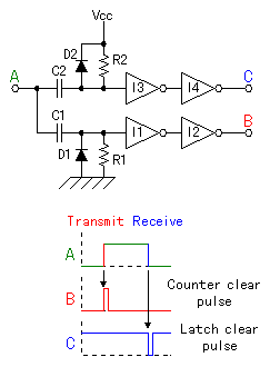 This circuit makes the counter clear pulse and the pulse to clear the latch of the display to use with the measurement counter (4553) to mention later. These pulses are made by differentiating the output of the time measurement gate circuit. This circuit makes the counter clear pulse and the pulse to clear the latch of the display to use with the measurement counter (4553) to mention later. These pulses are made by differentiating the output of the time measurement gate circuit.The A point changes into the H level from the L level when beginning to let out the ultrasonic. The electric charge begins to store up at the capacitor C1 by this change, the signal which was differentiated by C1 and R1 is applied to the inverter (I1) and the counter clear pulse develops with the output (the B point) of I2. Discharging by the electric charge which was stored up in C2 at this time but to flow through D2, the input of I3 is as the H level and the output (the C point) of I4 doesn't change. Next, when the ultrasonic reaches the reception sensor, the A point changes into the L level from the H level. The electric charge begins to store up at the capacitor C2 by this change, the signal which was differentiated by C2 and R2 is applied to the inverter (I3) and the latch clear pulse develops with the output (the C point) of I4.Discharging by the electric charge which was stored up in C1 at this time but to flow through D1, the input of I1 is as the L level and the output (the B point) of I2 doesn't change. The inverter of I1 to I4 are put to arrange the output wave form of the differentiation circuit. 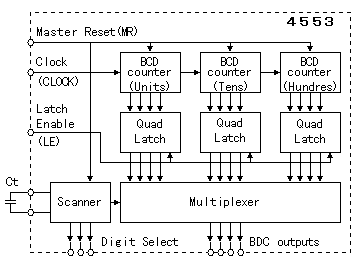 The 3-digit BCD counter IC(4553) is used to measure the propagation time of the ultrasonic. The block diagram inside is shown in the left figure. The 3-digit BCD counter IC(4553) is used to measure the propagation time of the ultrasonic. The block diagram inside is shown in the left figure.The reset of the counter and display scan's initialization are done when the master reset (MR) becomes the H level. At the circuit this time, the counter clear pulse is applied to the MR and it clears the counter in case of the measurement beginning. The display isn't cleared. The counter inside is cleared only. The measurement pulse is applied to the clock (CLOCK). The count up is done in the falling of the pulse. The measurement pulse is inputted to the clock terminal only at the time of the output of the time measurement gate circuit is the H level by the NAND gate. The contents of the BCD counter are taken in the quad latch register when the latch enable (LE) becomes the L level. When the LE is the H level, the taken contents are maintained (the latch). So, even if the contents of the BCD counter changes in the condition of the LE is the H level, the display doesn't change. After taking in the contents to the latch register in case of the measurement ending, until the time of the following measurement ending, the display doesn't change. This time, in the measurement interval, it has the about 63-millisecond period. So, the display changes the about 16 times within the 1 second. As for the measured figure of the 3 digits, the 1 digit is output by the multiplexer. The control of the figure to display is done by the scan oscillator. The frequency of the scan oscillator is decided by the value of the capacitor Ct. The frequency can be calculated by the following formula.
The electricity consumption can be lowered by displaying the 1 digit in the order. If using the high brightness LED for the LED, there is no problem with the light. 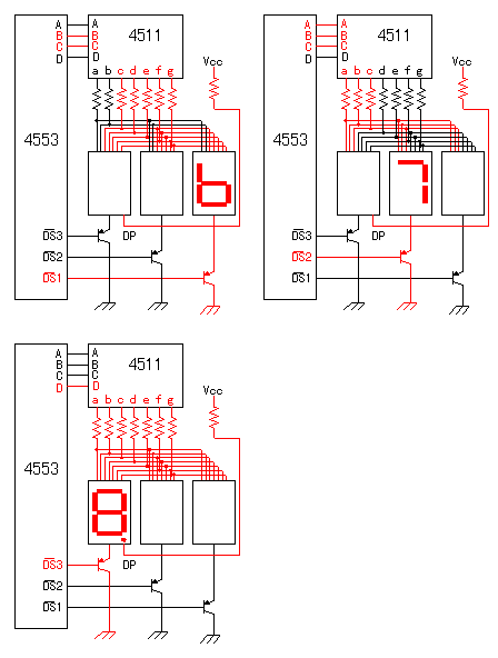 The measurement result is displayed in the three 7 segment LEDs. The control of the display is done by the display controlling function of the BCD counter. The control of the display is done at the cathode side of the LED. Therefore, as the LED, the cathode common type must be used. Also, the transistor to control must use the PNP type. 4511 is the decoder which changes the binary-coded decimal(BCD) code into the control code of the 7 segment LED. The left figure is the example which is displaying "8.76". It is displaying slowly. In case of the actual circuit, it seems to be displaying at the same time because it is changing at the scan period of about 1100 Hz. 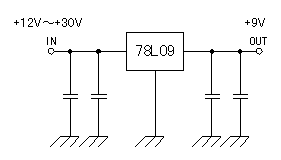 The circuit this time is using the various oscillators. The frequency of those oscillators is related with the measurement precision. So, the power supply voltage to use must be stable. Because the circuit is using the CMOS, the power supply voltage is OK rather than +5 V. The inner power supply voltage is made +9 V by the 3 terminal regulator. To make the output voltage of the regulator be stable, the input voltage must make about 3 V higher than output. The maximum voltage of the regulator is about +30 V. So, + 12V to +30V is supplied from outside. The circuit this time is using the various oscillators. The frequency of those oscillators is related with the measurement precision. So, the power supply voltage to use must be stable. Because the circuit is using the CMOS, the power supply voltage is OK rather than +5 V. The inner power supply voltage is made +9 V by the 3 terminal regulator. To make the output voltage of the regulator be stable, the input voltage must make about 3 V higher than output. The maximum voltage of the regulator is about +30 V. So, + 12V to +30V is supplied from outside.The consumption electric current is about 70 mA. The sound wave propagation speed in the air depends on the temperature. So, to measure the distance more correctly, it is necessary to revise according to the temperature. The sound wave propagation speed can be calculated by the following formula.
v = 331.5 + 0.6 * t [ m/sec ] t : The temperature (°C) The speed of sound at each temperature is as follows.
|