Parts explanation
for the stabilised power unit
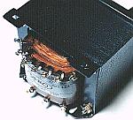 AC100 V is changed into AC30 V by this transformer. I am using the one of 4.8 A of the maximum electric currents of the side of AC30 V(Secondary). I am using 9Y3048 which is made by SINKO. The size of the transformer has the 86-mm width, the 96-mm depth, the 76-mm height.This size is the maximum which contained all prominences. The weight is 2.2 kg. It is the lump of the iron and the copper. 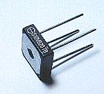 This is the rectifier which changes the alternating current(AC) into the direct current(DC). The four diodes are combined to do the full-wave rectification. Because the maximum of 5-A electric current flowed at the circuit this time, I used the 10-A one as the diode bridge. I am using S10VB20 which is made by SHINDENGEN. 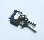 I am using this switch for ON/0FF of the power supply. The specification of the point of tact is 6 A at AC125 V. It is OK with the type which you like. The slide switch may be better because the power supply doesn't ON/OFF by the careless operation. There is one where the lever of the toggle switch has the lock mechanism. This time, I consider the power supply ON/OFF of the emergency and am using the one which doesn't have the lock mechanism. 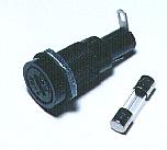 I put the fuse to the input circuit of the power supply for the safety. The maximum output of the power unit this time is 120 W(30V x 4A) in the calculation. Supposing that the efficiency of the transformer is 100%, the electric current on the side of AC100 V(Primary) is 1.2 A. Because the efficiency of the transformer is not 100%, any more electric current flows. I am using the 2-A fuse.  I am using this terminal as the terminal of the output. The output of the circuit this time doesn't connect with the grounding(The case). Because it is, you can use the voltage of the necessary polarity(The positive or the negative). I made the interval in the center of the terminal 18 mm. It is because I adjusted the position to the interval of the twin banana plug. It is OK even if you make the different interval. 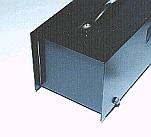 It is difficult to find the case with the appropriate size. I am using the one with the following size. It has the 130-mm width, the 120-mm height, the 230-mm depth. I used UB-13 which is made by the IDEAL company. My consideration point which chooses the case is hereinafter.
When mounting the transformer into the case, it is careful of the weight balance(The center of gravity). You mount it as the center of gravity becomes the center of the case as much as possible. When putting the carrying handle to the top of the case, you must consider the center of gravity. The carrying is easy when the weight balance is good. 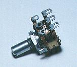 The variable resistor is used for the adjustment of the output voltage. Only the one variable resistor is OK but the voltage adjustment is sometimes troubled. A few turns of the knob change the voltage substantially. The subtle voltage setting is difficult. Therefore, with the circuit this time, I combine the 250 k-ohm variable resistor of the twin(For rough voltage adjustment) and the single variable resistor of 20 k-ohm(For voltage fine control). 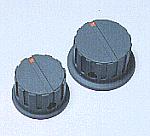 The voltage adjustment is easy when using the knob with the big size. You consider the whole design and you choose the one with the appropriate size. Of course, it is necessary that the axis hole of the knob and the axis diameter of the variable resistor agree. 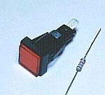 This lamp displays the operating state (ON/OFF) of the power unit. I am using the type that I can confirm the lighting-up condition even if I see by the slant as the lamp. I chose the LED of the resistor having-within for 12 V that the display part is wide. When making the LED light up at 12 V, the 16-mA electric current flowed. Because the voltage drop of the LED is about 2 V, the built-in resistor of the LED is 625 ohm((12V-2V)/16mA) in the calculation. Because it makes light up at the about 40-V voltage this time, I put the resistor for the electric current control in series. When connecting 1.8 k-ohm as the external resistor, the electric current which flows through the LED becomes about 16 mA((40V-2V)/(1800ohm+625ohm)). Because the consumption electric power of the external resistor is 0.5 W(0.016Ax0.016Ax1800ohm), I am using the 1 W resistor. The color of the lamp can use the color which you like.
That is, the color to use depends on the situation to make warn the person.Generally, it seems that it is using below.
This time, I use the red because the attention is necessary when the power unit is ON. (but not being to so worry) 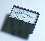 It displays the electric current of the output. The maximum electric current of the output is 4 A but depending on the voltage, the about 5-A electric current flows. Because it was dangerous when flowing through the continuation in more than 4-A electric current, I put the red mark over 4 A. The size has the 51.7-mm width, the 42.7-mm height, the 31.4-mm depth(excluding the terminal) . I used the MODEL:EA38YB which is made by the ERUNIK.K. "38" shows that the diameter of the meter installation hole is 38 mm. 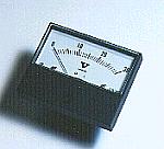 It displays the voltage of the output. Because the maximum output voltage is 30 V, I am using the 30 V voltmeter. The size has the 51.7-mm width, the 42.7-mm height, the 31.4-mm depth(excluding the terminal) . I used the MODEL:EA38YB which is made by the ERUNIK.K. "38" shows that the diameter of the meter installation hole is 38 mm. 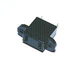 I am installing the two AC outlets for the other equipment in the back of the power unit. More outlets can be installed in the space of the back of the case. However, I consider the thickness of the AC cord and put the only two outlets. If using the thick cord, more outlets can be put. However, the thick cable with the big current-carrying capacity is necessary. 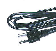 I am using the cord for 7A(700W). There is a way of using the connector as the way of connecting the AC cord. This time, I consider the following and put the AC cord to the power unit directly.
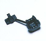 When passing the AC cord (the vinyl) through the hole of the metallic case without the protector, there is a gravity of the short-circuiting. This part is made with the plastic and can fix the AC cord on the case.  The name and so on are written at the front panel. As for the equipment of the maker, the silk print is used. The amateur doesn't have the such implement. This time, I print the name and so on to the paper and cover it with the transparent acrylic sheet. The thickness of the acrylic sheet is 0.5 mm. The acrylic sheet is fixed on the installation part of the meter and so on. It is necessary to be careful so as not for the warp to occur to the acrylic sheet when installing in the panel. 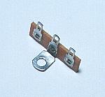 The AC cord connects with the power supply switch and the fuse respectively. I am doing the connection using the lug terminal. The arrangement of the wiring is easy in this way. Also, it is fixing the external resistor of the indicating lamp with the lug terminal too. 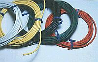 The maximum of 5-A electric current flows to the output from the secondary(AC30 V side) of the transformer. As for the wire to use for this part, the permissible current must be considered. This time, the permissible current of the wire which I am using is 7 A. The name of the wire is 0.75VSF. The copper wire has the small resistance. Because it is, it consumes the electric power when the big electric current flows through the wire and it generates the heat. The wire electric current permission value is decided to the value that the insulating material of the wire is endured by this generation of heat. Don't apply only the electric current below the permission value to the wire. The permission value is not the electric current which the copper wire dissolves in. 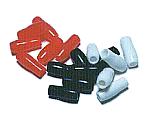 It is the pipe which is made from the vinyl. It puts on the soldering part of the wire. This pipe must be passed through the wire before soldering. After the soldering, it isn't possible to put on. There is one with the various size. As for me, only the 3 colors have the one with the same size. The original purpose of this pipe is the contact prevention. Because my use is the beauty when seeing, it isn't indispensable. 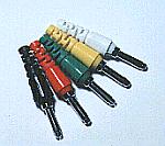 By installing this plug in the wire of the output, the wire can be easily attached or removed. 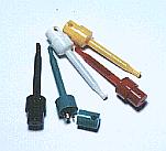 I put this plug to the tip of the output wire. The J-type reed goes out of the tip when pushing the top of the plug and can hitch to the terminal or the wire. Because the top turns back with the spring, the reed of the tip disappears and can connect tightly when relaxing the power to push. I used the big type to use for the power supply cable. 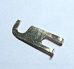 The output of the power supply this time doesn't connect with the grounding. Because it is, when using, you connect the grounding(Case) with either of the output terminal. When using as the positive power supply, you connect the ground terminal and the negative terminal with this bar. When using as the negative power supply, you connect the ground terminal and the positive terminal. Even if you don't connect it, the normal voltage is outputed between the positive terminal and the negative terminal. I made this bar using the brass with the 1-mm thickness. 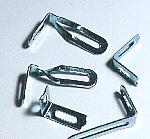 This is the metal fittings to install the switching regulator. This time, I am attaching the regulator perpendicularly by the convenience with the size of the case. I bent the metal fittings with the top by the 90 degrees in the relation of the installation position. 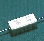 I put the resistor to measure the input electric current of the regulator. This is the cement resistor of 0.1-ohm 5-W. When the 4-A electric current flows, the electric power which is consumed with the resistor is 1.6 W((4A)2 x 0.1ohm). Because it put to measure the input electric current, it isn't indispensable. 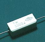 When the load isn't connected with the output, the energy which was stored up at the capacitor of the regulator doesn't decrease immediately. Therefore, even if the voltage adjustment is done in the no-load condition, the change of the output voltage is gentle and the voltage adjustment is difficult. I facilitated the voltage adjustment with this resistor. In case of the no-load condition, this resistor decreases the energy of the capacitor. I used the 300-ohm 5-W resistor. In case of the 30-V output voltage, the consumption electric power of the resistor is 3 W((30V)2/300ohm). I experimented on the change speed with the output voltage when turning the variable resistor for the voltage adjustment and decided this value. As the installation place, I connected with the voltmeter in parallel. When the load is always connected, it is not necessary. 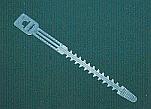 This ties the AC cord. This is convenient to put the cord in order. 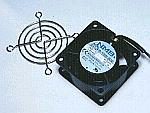 This is the fan to suppress the temperature rise of the regulator, letting out the heat of the regulator compulsorily out of the case. This is the fan to suppress the temperature rise of the regulator, letting out the heat of the regulator compulsorily out of the case.Because it had exceeded the allowable temperature (80°C) at the time of the maximum output after measuring the temperature rise of the regulator, I decided to install it. I used the model 2412PS-10W-B30 which is made by the MINEBEA CO., LTD. The size has the 60-mm height, the 60-mm width, the 30-mm depth. The sound is quiet. The strong wind can not be spouted but it is enough for the use this time. |
|||||||||||||||||||||||||||||||||||||||||