Practicable output range Practicable output range
When making the output to take out from the power unit big(Make the load resistance value small) gradually, it becomes the condition which can not keep the constant voltage.
The figure below shows the limit which can keep the constant voltage at each voltage.(Reference)
For example
In case of the voltage setting of 5 V, even if 4 A flow as the output current, the constant voltage can be supplied. The constant voltage can be maintained even if more than 4-A electric current flows at 5 V but it is better not to use because it exceeds the specification of the regulator.
In case of the voltage setting of 20 V, about 2.8 A become the maximum output current.
As for the maximum output current, the one with the higher output voltage becomes less. This main cause is due to the decline of the input voltage. When making the input voltage high, it is necessary to be careful so as not for the voltage in case of the no-load to exceed the maximum input voltage (40V) of the regulator.
Output characteristic
The output characteristic is changed by the set value with the output voltage.
The characteristic of the output when setting the output voltage to 5 V, 10 V and 20 V as the representative example is shown below.
Temperature rise
In case of the switching regulator, even if the output power changes, the regulator loss doesn't change mainly.
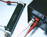
In the measurement this time, in the relation of the loading resistor (5-ohm 100-W), I measured the temperature rise of the regulator in the condition of the output current is 3.6A at the 18-V output voltage(65W). The regulators loss in this case is about 10 W.(5 W in each regulator)
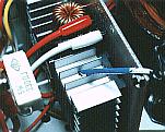
Because I installed the printed board of the regulator perpendicularly this time, I measured the temperature with the top of the radiator of the regulator. I measured in the condition to have installed the lid in the power unit to make the same as the actual use situation.
At first, I didn't install the fan. In the case, the temperature of the regulator had crossed the permission value (80°C). With the fan on the rear panel of the case, the temperature of the regulator became below the permission value in the situation of of the continuous duty in the maximum output in the power unit.
80°C is the upper limit with the operation ambient temperature. So, even if it exceeds this temperature, the regulator doesn't break immediately. I installed the fan for the safety.
Ripple
At the switching regulator, the ripple by the switching operation appears in the output.
At the circuit this time, I connect the capacitors of the low ESR in parallel and moreover am using the secondary filter but when the output power is big, the considerable ripple comes out. I attempted to connect the filter by the 330-µH coil and the 1000-µF capacitor with the output. There was not an effect which I expected. In case of 10 V, the ripple had increased. It may be that the value of the filter isn't appropriate.
The following photograph is the one to have observed the ripple voltage which appears at the output terminal in the no-load condition and the condition which connected the 5-ohm loading resistor.
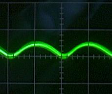 | 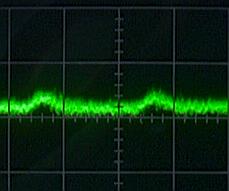 |
Vout = 30V, No-load
Ripple = 30mVp-p (0.1%) |
Vout = 5V, RL = 5-ohm
Ripple = 20mVp-p (0.4%) |
|
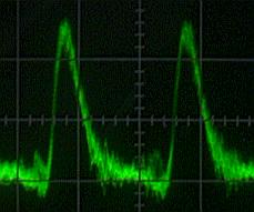 |  |
Vout = 10V, RL = 5-ohm
Ripple = 160mVp-p (1.6%) |
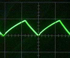
Vout = 18V, RL = 5-ohm
Ripple = 5Vp-p (28%) |
The range of the measurement in case of Vout =18V is 100 times of measurement ranges of the other photograph.
Because the voltage is changing, being small, the wave from can be thick seen.
|