Timer of PIC16F873
|
PIC16F873 has three kinds of timer. I will explain those specifications.
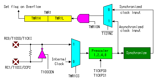
The overflow interruption can be enabled/disabled by setting/clearing TMR1 interrupt enable bit TMR1IE of PIE register. The interruption occurs when the counter rolls over to 0000h from FFFFh. 
In timer mode, Timer1 increments every instruction cycle (FOSC/4). Timer1 can be enable/disable by setting/clearing control bit ( TMR1ON bit of T1CON register ). Also, timer1 has an internal reset input. This reset can be generated by either of two CCP modules. When the timer1 oscillator is enabled by setting T1OSCEN bit of T1CON register. In the case, it connects a crystal oscillator with Pin 11 and pin 12. The oscillation frequency is possible to 200KHz. These pins combine the input/output pin of RC0 and RC1. However, the feature as the input/output pin is ignored. The setting of TRISC register is ignored too. In counter mode, Timer1 increments on every rising edge of clock input. When T1OSCEN bit of T1CON register is cleared, Timer1 increments on every rising edge of clock input on pin RC0/T1OSO/T1CKI( pin 11 ). When T1OSCEN bit of T1CON register is set, Timer1 increments on every rising edge of clock input on pin RC1/T1OSI/CCP2( pin 12 ). After Timer1 is enabled in counter mode, the module must first have a falling edge before the counter begins to increment. When started from the L level, the first rising edge isn't counted. If T1SYNC bit of T1CON register is cleared, the external clock input is synchronized with internal phase clocks. The synchronization is done after the prescaler stage. In Capture and Compare mode of CCP, timer1 is used. In case of the asynchronous counter mode, the counter can not be used for the capture or compare feature. As for the operation of the CCP, refer to CCP feature of PIC16F873.

Timer 2 is used for the PWM feature of CCP mainly. It is used to control the period of the continuation pulse. As for the operation of the CCP, refer to CCP feature of PIC16F873. |