 CCP1CON ( CCP1 Control Register ) 17h CCP1CON ( CCP1 Control Register ) 17h
This register controls the condition of CCP1 feature.
 | The value in the parenthesis is in the condition immediately after the turning on. |

 CCPR1L,CCPR1H ( CCP1 register ) 15h, 16h CCPR1L,CCPR1H ( CCP1 register ) 15h, 16h
This register is used when operating data by the operation of the CCP. The use changes with each mode.
As for the operation of the CCP, refer to CCP feature of PIC16F873.
 |
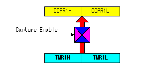
 Capture mode Capture mode
The contents of timer1 are stored at the time of the capture.
Two registers are combined and works as a 16 bits register.
|
 |
 Compare mode Compare mode
It sets the data to compare with timer1.
It combines and uses both registers as the 16 bits register.
|
 |
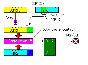
 PWM mode PWM mode
It sets data for the duty to CCPR1L.
CCPR1H is used for the processing inside and is a read-only register.
|

 PR2 ( PWM period register ) 92h PR2 ( PWM period register ) 92h
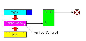
This register is used to set the period of the pulse signal by the PWM mode of the CCP.
 |
The contents of the PR2 register and the value of timer 2 are compared and the period of the PWM output pulse is decided.
As for the operation of the CCP, refer to CCP feature of PIC16F873. |
 |