Parts layout Parts layout
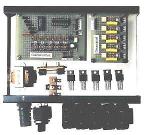
Before making holes, parts are temporarily put on a case, and a mounting position is checked.
TRIAC generates heat depending on the electric power to be used. Therefore, mounting with an interval is required.
Moreover, the space of wiring needs to be taken into consideration.
Making holes
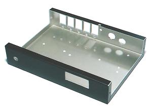
Holes will be made after the mounting position of parts is decided.
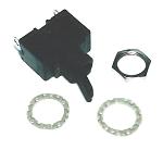
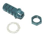
I made square holes for the output plug sockets and the thumbwheel switch using thread saw. And I made a little big circular holes for the power switch, the power cable and the pilot Lamp using reamer.
The attachment section of the power switch and the power cable protector used this time was long. So I made spacers to fit them.
Characters
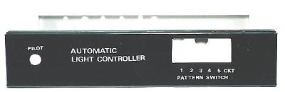
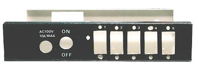
I wrote the equipment name and the name of each part to the panel of a case using the lettering sheet.
In order to protect the characters transferred from the lettering sheet, the lettering fixative is used.
 |
This is the photograph where the
thumbwheel switch was attached. |

Lettering sheet
This is the lettering sheet which displays a name on a case. |

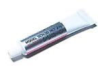
Lettering fixative
This is the solvent fixed in order to protect the character transferred from the lettering sheet. |
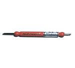
Tape cutter
This is the tool used when transferring the character of a lettering sheet on a case. If the head with a round tip is used, it can transfer finely. |
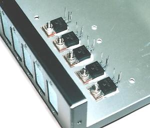
TRIACs are mounted first.
An insulation sheet is put between the TRIAC and the case. Silicone grease is applied to both sides of an insulated sheet. This is for raising thermal conductivity and making it heat get across to a case quickly.
Wiring of the AC circuit
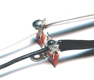
Wiring to five TRIACs was done using the lug terminal. In order to solder by bundling five wires, the big soldering iron of electric power is required. I used the soldering iron of 80W. |
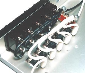
This is the picture which wired the MT2 terminals of each TRIAC and the outlets from the lug terminal. |
This is the picture which wired the MT1 terminals of the TRIAC and the outlets and the wiring to the TRIAC drive circuit. |
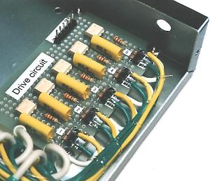
This is the picture of the wiring of the drive circuitt mounted into the case from the TRIACs. |
|
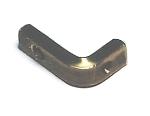
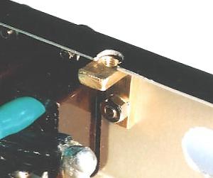
Five outlets are installed in the side of the case. There is possibility that a case is bent by the power when inserting or pulling out a plug. Therefore, I made a metal fitting which fix the lid and the panel of the case to improve the strength of the panel.
Metal fitting was made with bent stick. The thickness of the stick is 3 mm and the width is 6 mm. |
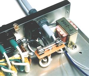 |
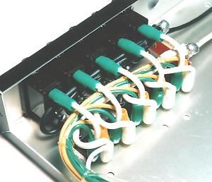
This is the picture of the wiring such as the AC input cord, the power switch, the fuse, the transformer. |
Wiring of the control circuit
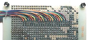
The BCD switches on a control circuit board and the BCD switches attached to the front panel are connected with wires. Attaching the BCD switches to the front panel should have been taken into consideration at the time of design. |
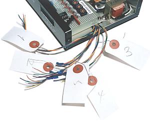
Wires are bundled for every switch and the tag which wrote the switch number is attached. Because, it is difficult to distinguish the kind of wires when mounting a control board on the case. |
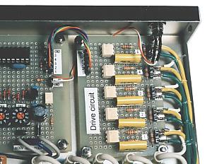
This picture shows the wiring of the AC power to the control circuit, the pilot lamp and the drive circuit. |
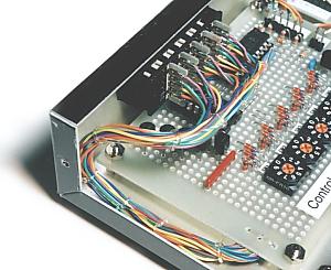
Wiring on BCD switches were bundled with the string of vinyl. In order to remove the PIC, it is necessary to remove the BCD switches outside from the front panel. Therefore, wiring is made somewhat long. |
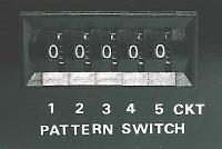
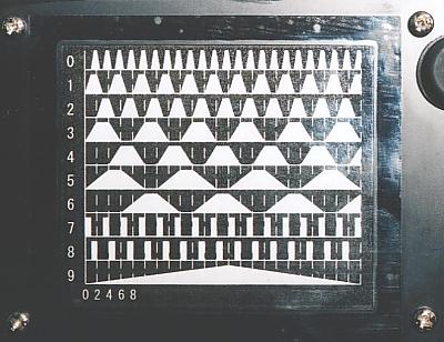
Blink pattern figure
The blink pattern of lamps can be changed with BCD switches.
I stuck the blink pattern figure by each switch position on the bottom of equipment.
|