Processing explanation for LED flasher 2
|
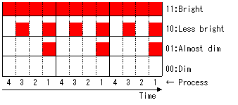
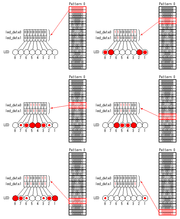
In the case of this software, the brightness control of LED is performed by main processing and the lighting position control of LED is performed by interruption processing. Four steps of brightness control is performed in LED brightness control.  The left figure shows the lighting control situation by the time progress about one LED. The part marked red is the time which the LED has turned on. When the brightness control data of the LED is 11, the LED lights up in all processes. When control data is 10, the LED lights up in process 1 and 3. It does not light up in process 2 and 4. In case of 01, the LED lights up only in a process 1. In case of 00, the LED does not light up. The left figure shows the lighting control situation by the time progress about one LED. The part marked red is the time which the LED has turned on. When the brightness control data of the LED is 11, the LED lights up in all processes. When control data is 10, the LED lights up in process 1 and 3. It does not light up in process 2 and 4. In case of 01, the LED lights up only in a process 1. In case of 00, the LED does not light up."led_data0" and "led_data1" are read in each process and each lighting control data of LED is checked. Thereby, lighting or putting out lights of LED in the time is judged. The brightness control data stored in led01, led10, and led11 is used for lighting control in each process according to lighting control data. The brightness of LED is finely controllable if the number of process is made many. However, many memories are needed. In this case, I made it four processes due to the program memory. In an actual process, it is carried out from a process 4 on account of processing. A process 4 is performed again after completing a process 1. In main processing, lighting control of LED is only carried out.Changing the lighting position of LED is performed by interruption processing. Interruption processing is performed for every 50 milliseconds using TMR0. In interruption processing, processing which changes the lighting position of LED is mainly performed. In case of this software, the number of the move patterns of lighting is three. It is the pattern 0 which the light of LED moves so that it may cross from both sides. In case of a pattern 1, light moves to the left from the right. In case of a pattern 2, light moves to the right from the left. The pattern 0 is set up in initialization processing. If interruption is performed, the state of a switch will be checked first. A pattern changes with the pushed switch. I made travel time of each LED the 100 milliseconds. This time is changeable every 50 milliseconds with the definition of "speed" data. By changing "speed" data, the ratio of the number of times of interruption and the number of times of move processing is changeable. In this time, because 1 is set as "speed", the interval of move processing is 100 milliseconds. If "speed"is set to 0, the interval of move processing is 50 milliseconds. If "speed" is 1, interval is 100 milliseconds. If "speed" is 2, the interval is 150 milliseconds. In LED lighting move processing, ten control data registered for every pattern is copied to led_data0 and led_data1 at intervals of 100 milliseconds. The LED flasher which has the tail of the light has been complete by above mentioned processing. list p=pic16f84a
include p16f84a.inc
__config _hs_osc & _wdt_off & _pwrte_on & _cp_off
errorlevel -302 ;Eliminate bank warning
;****************  Label Definition  ********************
        cblock  h'0c'
The data area is automatically assigned from 0ch by CBLOCK directive. ENDC is used for the ending of assignment.The purpose of each data area is shown below.
In addition, the following labels are defined.
;*************  Pattern Data Definition  ****************
; 1 bright  1 less bright  0 almost dim  0 dim
; 1         0              1             0
This is lighting pattern data of each LED. 2 bytes are a pair. Each bit corresponds to the LED, and upperside and lowerside combine and are used. In case the upperside is 1 and lowerside is 0, it is interpreted as 10 and it shows "less bright". 3 patterns are defined. ;**************** Program Start ***********************Instruction is executed from Zero addresses of the program memory when making the power ON of the PIC. Moreover, the start address of interruption processing is h'0004'. ;**************** Initial Process *********************
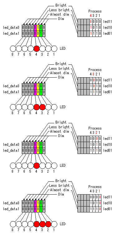
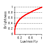
;**************** LED control Process ******************Lighting control of LED is performed in 4 steps. An LED lighting-up control according to the light specification by the LED is executed at each time. When making light up most brightly, all four times make light up. When making light up less bright, it makes light up only twice in four times. When making light up almost dim, it makes light up only once out of four times. In case of dim, all four times don't make light up. Each time is called in the name of "Process". Process is cyclically executed as follows. Process 4 ;****************** bit0 for process1 *******************In each process, the processing of each LED is executed. Each LED corresponds every bit of the memory with byte like bit0 to LED1, bit1 to LED2 so on. In one process, it is processed from bit 0 to bit 7 to continue.  The data which specifies the brightness of LED is set to led_data0 and led_data1. A setup of this data is performed by the interruption processing explained later. led_data0 is the upperside bits and led_data1 is the lowerside bits. In case of the bit 0 of led_data1 is "1" and the bit 0 of led_data0 is "1", the control data becomes 11. This is specification "bright". When this data is 10, it is the specification "less bright". When this data is 01, it is the specification "almost dim". When this data is 00, it is the specification "dim". The data which specifies the brightness of LED is set to led_data0 and led_data1. A setup of this data is performed by the interruption processing explained later. led_data0 is the upperside bits and led_data1 is the lowerside bits. In case of the bit 0 of led_data1 is "1" and the bit 0 of led_data0 is "1", the control data becomes 11. This is specification "bright". When this data is 10, it is the specification "less bright". When this data is 01, it is the specification "almost dim". When this data is 00, it is the specification "dim".The LED lighting control with each process is due to the data which is specified by led11, led10 and led01. In case of 00, because it is dim, it isn't laying down data. Data 11 means bright so it may not be necessary to lay down data. In my case, I consider to control brightness and the data is laying down. 11111010 is set to led10. Because it is providing only 4 processes in this time, it isn't using 4 bits of the higher rank. 4 bits of the lower rank correspond to each process. The bit0 is for process 1, the bit 1 is for process 2 so on. As for each bit, 1 means going-out and 0 means lighting-up. So, when the light specification is 10, a going-out control is done in process 1 and 3, and a lighting-up control is done in process 2 and 4. The processing result of each bit in the process is preserved temporarily in port_work. When the processing of all bits completes, the data of port_work is written in PortB. Each LED is controlled at this point. In the animation of this explanation, it changes a process every 500 milliseconds. However, the processing of 1 actual process ends within about 100 microseconds. Because it is a speed with 10,000 times in 1 second, the condition that the LED is blinking can not be seen with the eyes. The difference in brightness can only be seen.  The brightness of LED is not proportional to the value of current. When there is little current, LED begins lighting. It is said that the brightness of man's eyes is proportional to the 1/3rd power of luminosity. When luminosity is small, change of brightness is taken in sensitively. However, change of brightness is not felt even if luminosity will change, if it becomes a certain amount of brightness. There are 4 times of luminosity differences in bright and almost dim. However, I can not recognize a difference as much as it to the look. The brightness of LED is not proportional to the value of current. When there is little current, LED begins lighting. It is said that the brightness of man's eyes is proportional to the 1/3rd power of luminosity. When luminosity is small, change of brightness is taken in sensitively. However, change of brightness is not felt even if luminosity will change, if it becomes a certain amount of brightness. There are 4 times of luminosity differences in bright and almost dim. However, I can not recognize a difference as much as it to the look.The way of increasing a process as the way of putting a difference to the brightness is thought of. The luminosity difference between "Bright" and "Almost dim"" becomes by 8 times when repeating process 4 itself four times more. I think that the difference with brightness can be recognized by this. ;********** Interruption process beginning *************TMR0 time-outs within 50 milliseconds and the interruption of the processing occurs. The execution address moves to 0004 address of the program memory when the interruption occurs. In this software, because goto instruction to the interruption processing is written in 0004 address, the processing jumps there. To do first by the interruption processing is the saving of the contents of the W register and the STATUS register. These registers are used for the processing before interruption. So, after the interruption processing ends, the original processing doesn't work normally when not becoming the value which is the same as the interruption time. Next, whether it is a timer interrupt is checked. In the processing this time, it isn't using except the time-out interruption of TMR0. So, this processing is laid down for the safety. In case of interruption except the time-out, it jumps for the initialization processing. ;***** Timer interruption process (50ms interval) ******After confirming the time-out interruption of TMR0, it erases the interruption display of the time-out. When not erasing this flag, after ending interruption processing, the interruption has occurred immediately. In case of being in the time-out, because the contents of TMR0 become 0, 50 milliseconds value should be set again. ;****************** Key Scan Process *******************In this processing, it is confirmed whether the switch which changes the lighting pattern of LED is pushed. If a switch is pushed, the bit of PortA to which the switch is connected will be set to 0. The pushed switch can be known by checking the bit which is 0. When a switch is pushed, the pattern number corresponding to a switch is recorded on "ptn_save". An execution judgment of pattern processing is made at the last of Key Scan processing. The interruption occurs every 50 milliseconds with TMR0. The execution judgement of the pattern processing is done by the value of counter. It executes pattern processing if the result which subtracted 1 from the value of counter becomes 0. For example, when the value of counter is 2, pattern processing is executed once to the interruption with twice. In this case, pattern processing is executed in 100 milliseconds interval. When the value of counter is 3, it is 150 milliseconds interval. The value of counter is defined by "speed" data. When "speed" is 1, counter is set to 2 and the pattern processing becomes 100 milliseconds interval. ;***************** Pattern Process *********************At the head of the pattern processing, the value of counter is set again. It is to make an interval of the execution of the pattern processing constant. After that, it checks the pattern number which is recorded to ptn_save and it jumps to the corresponding pattern processing. ;********************* Pattren 0 ***********************  At the head of each pattern processing, it implements the check of the pattern number. When the number is the same, it finds that it is last pattern processing continuation. In the case, the data after the data which was set last time is set to led_data0 and led_data1. When the number isn't the same, data at the head of the corresponding pattern is set to led_data0 and led_data1. In the pattern processing, it sets the data which was defined in Pattern Data Definition to led_data0 and led_data1 in the order. When "speed" is 1, it is established in the 100 milliseconds interval. If pattern data is set to led_data0 and led_data1, the pattern counter( ptn_counter ) will be counted up and it will jump to the interruption ending processing. In the animation, it is setting pattern data in the 200 milliseconds interval. ;************ END of interruption process **************In the interruption end processing, it returns STATUS register and W register to the condition before interruption. It returns STATUS register first and it returns W register next. The point which is careful here is the way of returning W register. The contents of the STATUS register have changed when restoring W register with "movf" instruction. Therefore, it uses "swapf" instruction twice and it returns W register to the origin to avoid a change in the STATUS register. Interruption processing is completed by "retfie" instruction. |
|||||||||||||||||||||||||||||||||||||||||||||||||||||||||||||||||||||||||||||||||||||||||||||||||||||||||