PIC16F84A PIC16F84A
PIC16F84A is used in this circuit. In PIC16F84A, the oscillator upto 20MHz can be used. It is made to operate by 4MHz in the case of the software currently introduced here. |
Voltage regulator (7805)
This device is used in order to get the voltage of stable +5V.
1A type is used.
When there is little LED made to turn on simultaneously, 100mA type 78L05 can be used.
 |
Light Emitting Diode
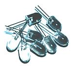
The high luminosity type red LED with a diameter of 10mm is used.
A part number is unknown.
Recommendation lighting current is 20mA.
|
Resonator
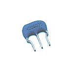 This device is a ceramic oscillation element for the clock oscillation of PIC. Because the capacitors for an oscillation are built in, wiring can also attain simplification. This device is a ceramic oscillation element for the clock oscillation of PIC. Because the capacitors for an oscillation are built in, wiring can also attain simplification.
Oscillation frequency is 4MHz. |
Switch
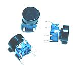
These switches are used in order to choose the lighting pattern of LED.
These are non lock type small switches.
|
IC socket
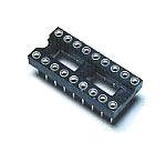 This is a socket for mounting PIC16F84A on a printed circuit board. This is a socket for mounting PIC16F84A on a printed circuit board.
It is more convenient to use a socket, because the software of PIC may be rewritten.
|
Multilayer ceramic capacitor
These capacitors are used for oscillation prevention of 3 terminal regulator.
Even if it does not attach, there is usually no problem.
However, to attach as foundations is safer. |
Resistor
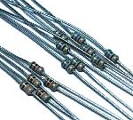
In this circuit, there is no circuit through which big current flows.
Therefore, the resistor of 1/8W type is used altogether. |
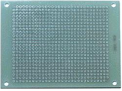
Printed board
The universal printed circuit board with 24 x 30 holes is used.
|
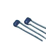
Wiring terminal
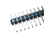
The pin type terminal is used as a power supply input terminal. |
Stud
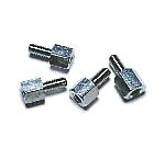
The metal studs are used as the leg. There is no metal necessity. |
|