Circuit explanation of LED flasher 2
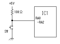
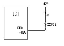
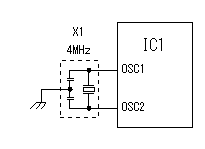
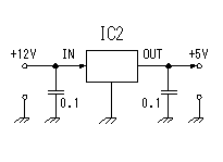
 In this circuit, three pins from RA0 to RA2 are used as key input. The pull-up of each pin is carried out by the resistor of 10Kohm. By this, when the switch is not pushed, the pin is held at H level (+5V). It will be set to L level (0V) if a switch is pushed. When a switch closes, the phenomenon of chattering occurs. This phenomenon occurs with the point of contact bound when a switch is closed. It is the phenomenon that the opening and closing of a switch is repeated in short time. In this circuit, the condition of a switch is detected with the software scanning. It is judged that the switch will be closed at the time of scan if it is L level. By this software, an operating condition is held until other switches will be closed, if it detects that a certain switch was closed. Therefore, the prevention circuit of chattering is not prepared.  Eight pins of RB0 to RB7 are used as an LED control pin. The anode side of LED is connected in +5V. Lighting of LED is controlled by PIC via a resistor in the cathode side. Therefore, when the output of PIC is H level(+5V), LED puts out the light and, in the case of L level(0V), LED turns it on. The resistance for current control of LED is calaculated as follows. The lighting recommendation current of LED used this time is 20mA. ( Power supply voltage - LED lighting voltage(2V) ) / LED lighting current = ( 5V - 2V ) / 0.02A = 150 ohm Because I had no 150 ohms resistor at hand, I used 220 ohms. In this case, the current of LED is ( 5V - 2V ) / 220ohm =14mA.  The timer function of PIC is used for the processing which moves the lighting position of LED. When man looks at the lighting situation of LED, it is not meaningful if too quick. In this circuit, it is the purpose to show so that lighting of LED may drag on. In order to lengthen time of a timer, 4MHz resonator is used. The period with 4MHz frequency is 1/4,000,000 = 0.25 microseconds. Because 4 periods (the clock) are necessary to the count of the timer, a count is downed with the timer every microsecond. Because a prescaler of 1/256 is used for the input of timer, actually, a count is downed with every 256 microseconds. When making the initial value of the timer as 195, the time-out becomes 256Ásec/count x 195count = 49920Ásec = 50msec.  A 3 terminal regulator is used to get +5V power from the +12V. I used a 1 A-type regulator(7805). In the software this time, two "bright", two "less bright" and two "almost dim" as the LED which light up at the same time. It is about 60mA even if it supposes that four LEDs light up at the same time. It is less than 100 mA even if it adds the consumption of PIC. In case of it, 100 mA type regulator(78L05) can be used. |