Detailed photograph of making holes
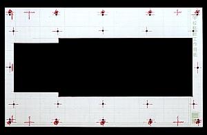 |
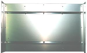
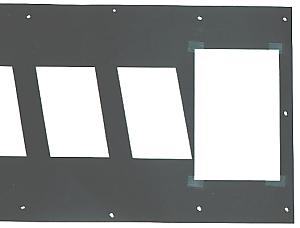
Before making holes to the case, I made the pattern to decide the position of the holes with a little thick paper. The position of the holes for the display part is confirmed by putting an actual display part to the pattern. At the pattern, the screw hole for the acrylic board to put to the front of the display part is drawn. First I planned to open these holes at the 10-mm position from the edge of the case. However, this position bumps with the bottom of the case. Therefore, I modified into the 15-mm position. |
 |
Before making holes for the display part at the case, a supporter is put. An edge in the longitudinal of the cover which was used this time isn't bent. So, the longitudinal bends easily. There is possibility that the cover bends when making holes without reinforcing. The holes which put a display part are used for the installation of the angle.  |
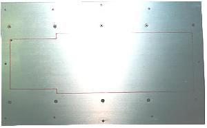 |
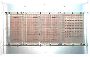
The position of the holes are drawn at the cover using the pattern. The photograph on the left is in the condition which put an angle. The holes to fix an acrylic board are opened at the edge of the cover. Originally, the fixing of a cover and a bottom board is only 4 positions which are at the side of the case. A fixing screw isn't put to the longitudinal of the cover. In case of the equipment this time, most of the circuits are put to the cover part. I thought that the strength wasn't enough only by the angle. The holes of the central top and the bottom are the holes to fix a cover on the bottom. |
 |
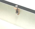
The photograph on the left is the photograph which saw the condition which put angles from the back. |
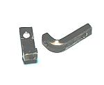  |
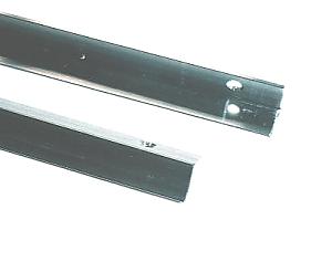
This is the metal fittings to fix a cover at central. It is made with brass stick with 3-mm thickness. The female screw is opened. |
 |
The hole for the display part is an about half with the area of the cover. Don't depend on the angle. It is necessary to do an attention for the work which makes holes. |
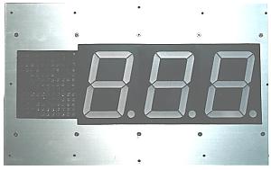 |
The photograph on the left is the photograph that a display part is put to the case. It is necessary to make the height of the display part the same as the surface of the case. A double nut is used for the stopper for the display part. |
 |
The photograph on the left is the photograph which saw the condition which put a display part from the back. |
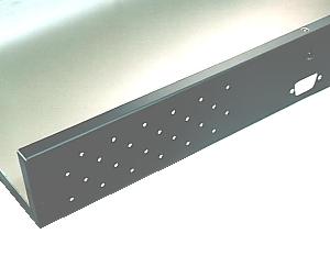 |
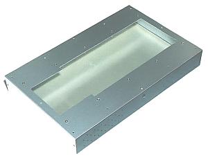
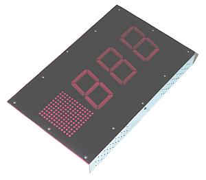
At the bottom of the case, a hole for DSUB connector and holes for the ventilation are opened. At the equipment this time, a lot of heat isn't generated. The holes for the ventilation are opened to the side of the case for the safety. The holes for the ventilation are opened on either side of the center which DSUB connector is put to. Also, the holes are opened to the opposite side, too. 96 holes are opened. |
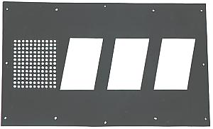 |
A mask is put to the surface in the display part with the black paper. It is to hide installation screws and so on. |
 |
The LED which is used for the category displaying is designed to let out a blaze to the front. The brightness falls when seeing from the diagonal. Therefore, white paper is used to diffuse light. Also, to make the displaying of each LED clear, a circular hole is opened to the mask.  |
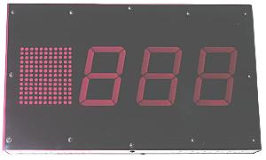 |
A purple acrylic board is put to the surface of the display part for a character by the LED to be clearly seen. Because a photograph at the photograph on the left was taken with the strong light, the display part was looked clearly. In usual light, only the character that the LED lights up is clearly displayed. |
 The installation of the display part was complete. |
|