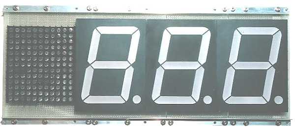
Detailed photograph of Display panel
 You can jump to the page of the explanation when you click the part where the pointer become the hand. |
||
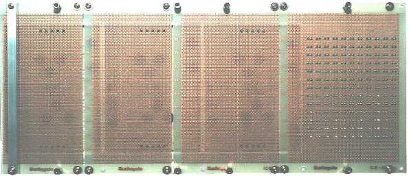 A control unit and a diode matrix are put using 10-mm stud. A control unit is put to the left side and a diode matrix is put to the right. At the photograph above, the studs for its purpose are already put. |
||
|
||
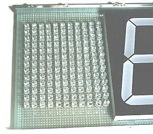 |
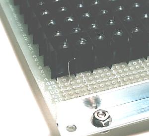
143 LEDs are used for the category displaying. The height of these LEDs is made the height which is the same as the 7 segment LED. To put an LED to the same height I worked as follows. It passes the lead wire of the LED through the hole of the printed board from the component side. After that, it puts a component side on the flat board, having it down. In this way, it is possible to make the height which is the same as the 7 segment LED. The attention is to put an LED perpendicularly. At first, it solders only one lead wire of the LED. After correcting the position of the LED, it solders another lead wire. In this way, the position of the LED can be arranged beautifully. |
|
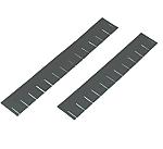 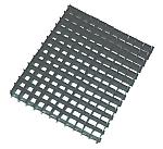 |
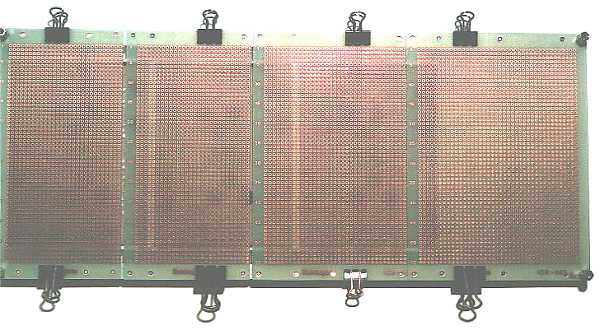
When the LED lights up, a character isn't cleared when the light leaks to the LED next. Therefore, a enclosure which blocks light is put among the LEDs. Black paper is used for the enclosure and slits are put to the interval of the LED. It is made a pin grid array format by combining up and down. |
|
 |
The paper which composes the enclosure is fixed with the glue so as not for the grid to become apart after combining. Also, the stopper with wire is put to the bottom of the grid for the LED to become of the grid central. |
|