 |
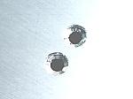
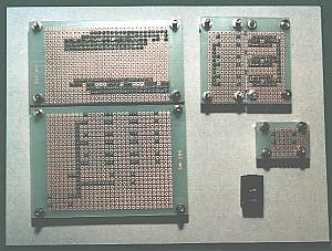
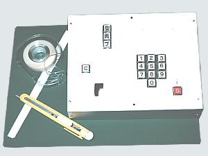
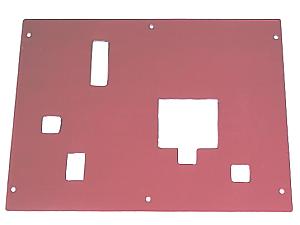
I made holes on the paper and install the parts and I decided the position of the holes.
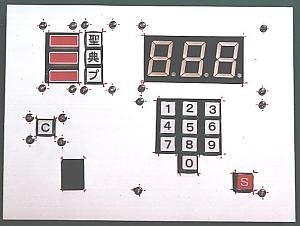
I did the flow of the key operation as follows.
Category select -> Number select -> Send data
Key operation is done for the lower right from the upper left.
A Clear key isn't usually used, so, it is put on the left side.
When an a little biggish hole has been opened, the size of the hole can be adjusted with the paper. When the size of the hole isn't adjusted by the paper, there is possibility to make a mistake in the size of the actual hole. So, the size of the hole with needed size should be corrected with the paper.
The position of the hole can be confirmed when marking a center of the hole. |
|
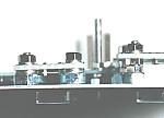
 | This is the photograph which looked a temporary putting condition from the back. |
|
|
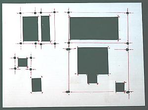
After removing parts, the position of the holes for the screws and for the parts are corrected.
The red line was drawn to confirm whether or not the installation position of the part fitted the edge of the case. |
|

| This is in the condition to have drawn the position of the holes at the case using the pattern above. |
|
|
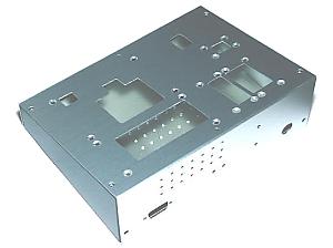
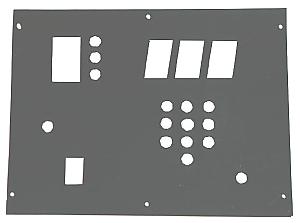
The hole opening at the case ended.
Plate screws are used for the installation of the LEDs and the switches. The head of the screw doesn't protrude because the head of the plate screw is flat. To make a screw level with the panel surface, a screw hole is shaved in plate-shape. A plate part is shaved in plate-shape using the 6-mm drill.
|
|
|
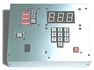
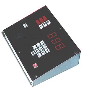
This is in the condition which the parts were put to.
The height of the part is different about the LED and the switch. So, nuts or washers are used for the adjustment of the height.
|
|
Back |
Bottom |
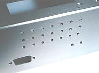
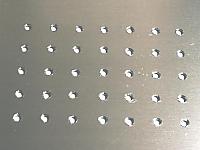
Ventilation holes
A little heat occurs to the console unit with the power unit. So, the ventilation holes are opened to discharge the heat at the back of the cover and the bottom of the case.
|
|
|
Pattern to make holes of the blindfold sheet and the acrylic board
It makes big holes in the part of the switchs. It hits against the actual panel and it pastes paper to fit the position of the switch and it adjusts the size of the hole. By this, the pattern which doesn't have a prank can be made. |
|
|
Blindfold sheet
Plate screws and so on are masked with the black paper. By this mask, it isn't possible to be seen from outside except the buttons of the switch and LEDs. |
|
|
Acrylic board
A purple acrylic board is put to the operation surface. With this, it becomes possible to look at the LED clearly. The purple suits to clear the displaying of an LED most. |
|
 The part of the panel was complete.
 |