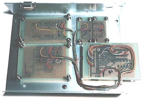
Wiring of Console controller
 Wiring is fixed using the holes of printed board with the vinyl string.
 |
|
Wiring to switches and LEDs are tied with the vinyl wire.
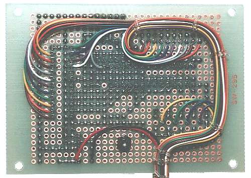
These wiring is fixed using the small hole which was opened at the end of each printed board. By this, when removing a control printed board, the influence over the soldering part of the wiring can be prevented.
Because diodes are added between the switch and IC2 after doing this photography, the wiring is slightly different from the last one. |
|
|
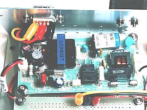
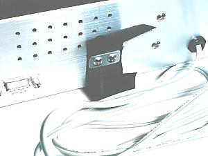
A power unit is put using the screw of the 7 segment LED.
At first, I planned to put a power unit to the back panel. Therefore, the position of the hole of the power unit and the position of the screw of the 7 segment LED are different little. It is put diagonally but there is no problem.
The length of the wiring with the power unit and the wiring with the DSUB connector of the back panel is long a little. This is because the wiring makes not become troublesome when removing control unit. |
|
Wiring for the power unit |
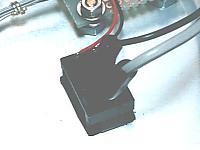
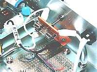
Wiring for the power switch |
This is wiring of the relation of AC100V.
I used a lug terminal for the wiring. However, when the wire of the power unit is long, it is possible to be directly wired to the fuse and the power switch.
|
|
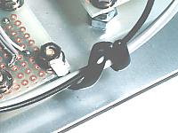
Support for the AC cable |
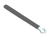
Coaching clip |
Because the AC cable inside is slightly long, a Coaching clip is put to the way. A clip is put to the screw of the clear switch. Because the clip is made with soft metal, it can be easily bent with the hand. The surface of the clip is covered with the vinyl for the insulation.
|
|
 | The AC cable outside can be tied with the tape. |
|
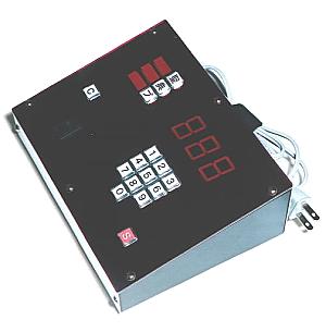 The hardware of the console unit was complete.
 |