I will introduce the way of making the case which used the acrylic board on this page.
I used "Bending apparatus-2" to bend the acrylic board.
 Drawing of case Drawing of case
Bottom
The after work is easy when bending a cover installation part first.
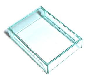
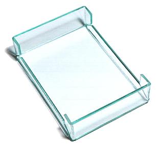
Cover
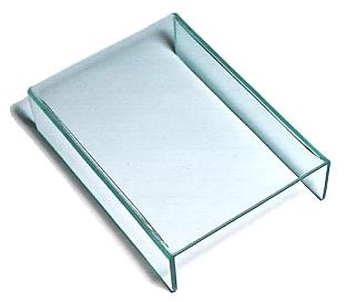
A glass colored acrylic board was used for cover.
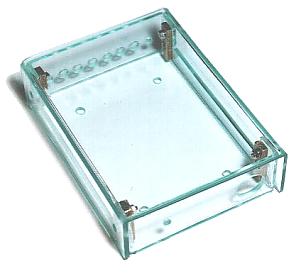
I made a cover after making the bottom.
The cover is bent according to the size of the bottom.
To make length on either side the same, I was cut after the bend of the cover was ended.
Making holes
 For fixation the terminal For fixation the terminal
It makes holes to install a terminal for the output signal. To decide the position of the hole, I used the printed back panel to the paper.
For fixation the power supply connector
It makes a hole which installs a power supply connector. To decide the position of the hole, I used the printed back panel to the paper same as terminal. It makes needed size using the reamer because it isn't opened only by the drill. If approaching needed size, it confirms size frequently.
For fixation the anntena
To decide the position of the hole, I used the printed back panel to the paper.
For fixation the control board
It mounts the control board on the center of the case. The power supply connector has depth. So, it pays attention so as not for the screw of the board to touch.
For fixation the cover
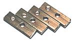
This time, I mounted screws for the fixation on the side of the case. Because the thickness of the acrylic board which was used this time is 2 mm, it can make a directly female screw at the acrylic board, too. I made a female screw using the brass board with 3-mm thickness. It is fixing a brass board on the bottom using the plate screw of 2 mm.
|