PIC16F84A PIC16F84A
This PIC analyzes the control code to take from the transmitter and when receiving a normally code, it controls a relay.
Low noise operational amplifier ( LM358 )
The voltage of the signal which detected a high frequency isn't enough for PIC. The input voltage which PIC needs is made by amplifying by this amplifier. The operation is similar to the comparator. The output becomes an open condition when the input voltage of the positive terminal exceeds the voltage of the negative terminal. For the mounting space, I used the operational amplifier of the 8 pin type.
FET for the high frequency amplification ( 2SK439 )
This transistor is used to amplify a received electric wave.
Transistor for relay drive ( 2SC1815 )
This transister is used to drive the relay.
3 terminal regulator ( 78L05 )
3 terminal regulator is used to make the power (+5V) of PIC from +12V power.
A 100mA type is used.
IC socket
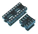
These are 18 pins socket for PIC16F84A and 8 pins socket for LM358.
I used a round hole type for PIC but you can use a board type, too.
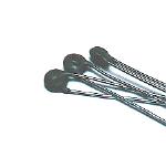
Resonator
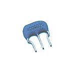
This is the oscillation device to make the clock of PIC. A ceramic vibrator and capacitors are incorporated.
The clock frequency this time is 4 MHz. It is possible to make do the operation of PIC16F84A with the a maximum of 20MHz clock.
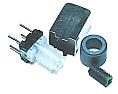
High frequency transformer
This transformer is made to resonate with the frequency of the transmitter. With it, only the electric wave of the transmitter can be received. The transformer which was used this time is the type which is called 7S80 for about 80 MHz. The size is 7 mm.
The specification when you make a coil is hereinafter.
 |
The coil on the side of the resonance is 6 turns with center tap.
The coil on the side of the output is two turns.
|
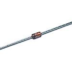
Diode for the detection ( 1N60 )
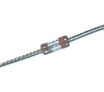
A diode for the high frequency is used for a detection diode, because it rectifies an about 80-MHz high frequency directly.
I used a Germanium diode.
Zener diode ( RD5A )
When not using this diode, the change range of the output of LM358 is 0V-12V.
The maximum voltage of the I/O port of PIC is 5V. Because it is, the voltage which is applied to PIC is controlled to 5V by this diode.
Output relay ( G5V-1 )
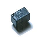
This is the small relay which is made by the OMRON Inc..
 |
| Drive voltage | DC 12V |
| Number of contacts | 1 |
| Contact capacity | 30VDC | 1.0A |
| 125VAC | 0.5A |
| 80VDC | 0.3A |
|
Light Emitting Diode

The equipment this time is using two control codes.
I used LEDs with different color as the understanding of control code.
Red is used for circuit 1 and green is used for circuit 2.
Brightness type is used.
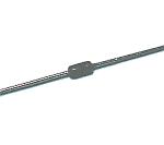
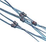
Transistor protection diode ( 1S1588 )
This diode is used to prevent from transistor destruction by the back electromotive force of the relay.
Resistor
At the circuit this time, the resistors with 1/8 W permission electric power are used.
Ceramic capacitor
Ceramic capacitors with good high frequency characteristic are used for the resonance circuit.
Multilayer ceramic capacitor
The unnecessary high frequency which influences circuit operation is bypassed with these capacitors.
This capacitor has a large capacity comparatively with 10000pF but it is small.
Printed board
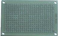
I used the boad with 15 holes x 25 holes.
Ground board
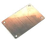
The circuit this time handles a high frequency. To ground surely, I put a brass board with 0.5-mm thickness under the printed board.
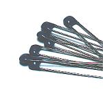
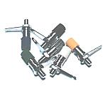
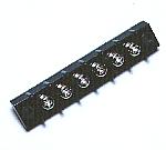
Wiring terminal
This terminal is used for the wiring with the outside parts such as the power supply, the antenna and the output of the relay.
Stud
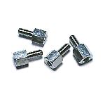
This stud is used to fix a printed board on the case.
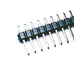
Antenna terminal
This is the terminal to connect the outside antenna.
Output terminal
This is the terminal to connect circuits on the outside to correspond to the control code.
AC adapter
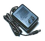
This is the power supply adapter to get DC +12V from AC 100V. The 300-mA electric current can be passed.
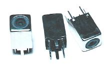
Power supply connector
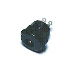
This is the connector to connect the AC adapter.
Case
I housed a receiver in the case which was made by bending acrylic board.
Back panel
I put the panel which wrote the name at the back. It is the one which was printed in the color to the OHP sheet. I put in the white paper for the letter be able to be clearly seen.
Leg
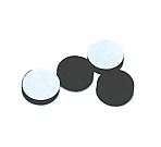
This is the leg to have put to the part in the bottom.
These legs are to protect the case when putting the measurement equipment.
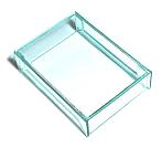
Terminal cover

This is the cover which protects the connection part of the wiring.
Because the connection part is the circuit inside, it isn't touched. I used because I looked pleasant
|