Circuit explanation of Digital Clock
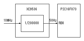 10MHz clock which have ultra precision is used for the input clock. This clock is converted into 50Hz which is 1/200000 by CPLD (XC9536). It is to make time setting correct that it didn't change into 1Hz. When making 1Hz, the setting of a time becomes a second unit. So, it isn't possible to do setting in the second correctly. In case of 50Hz, because it is adjusted in the 20-millisecond precision, there is no problem in case of practical use. A 50Hz clock is connected with the RB0 port of PIC. The RB0 port can make have the function to do interruption in the change of the input signal. This time, it detects the rising edge of the input signal and the interruption occurs. It counts this interruption 50 times and recognizes 1 second. This frequency convertor can be made with the circuit using three 74HC390 to be introducing "Frequency divider". 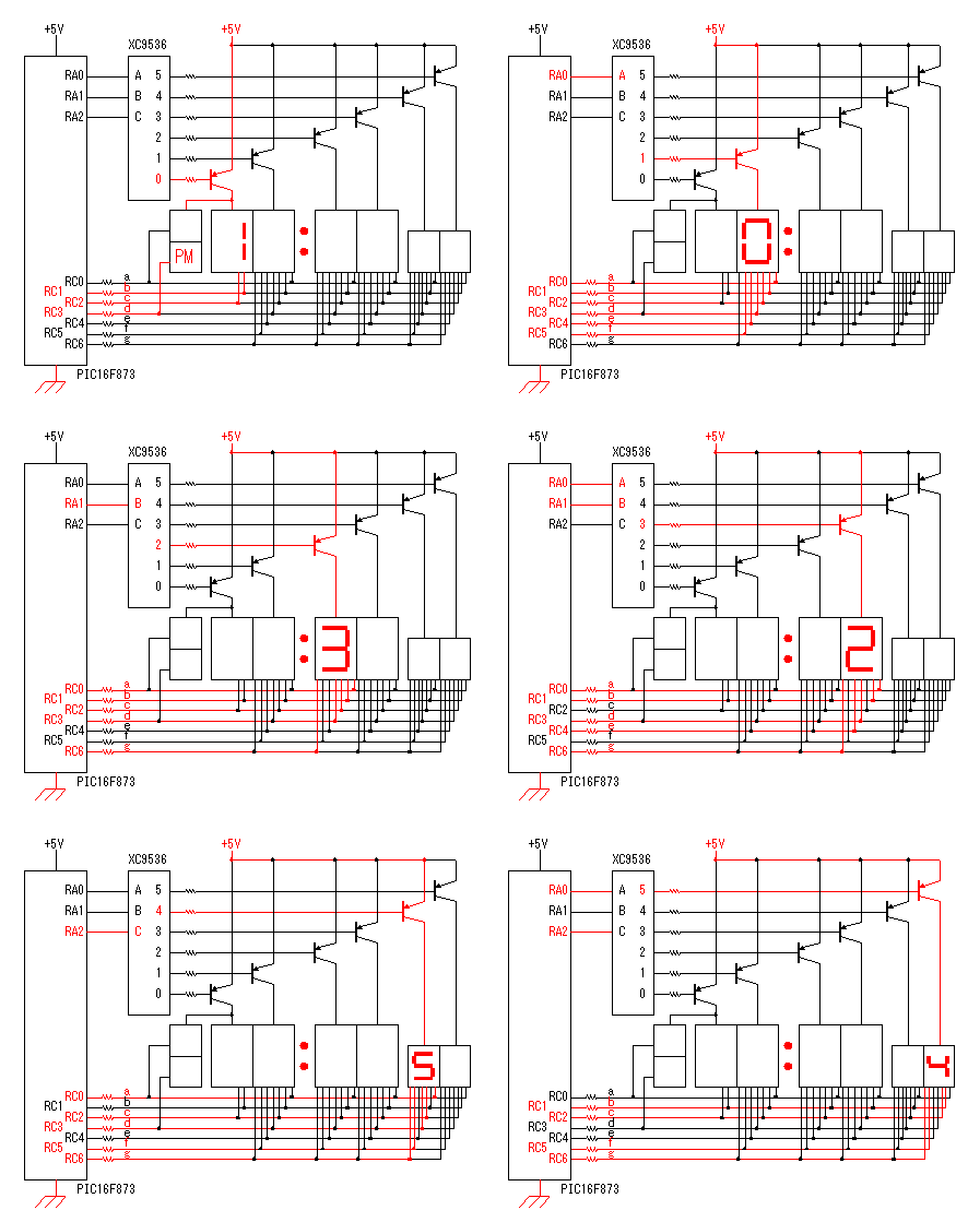 The figure on the right is displaying the condition to be displaying 10:32:54 p.m. switching every 500 milliseconds. In the switching time of the actual circuit, it is 1 millisecond. So, all digit sees to be displayed at the same time. The light of the LED is 1/6 compared with the continuation lighting-up. The specification of the display position is controlled by the binary signal which is output from RA0, RA1 and RA2 port of PIC. This signal is decoded in CPLD and eight kinds of signals are made. This time, six kinds are used. Only the transistor which corresponds to the L level decoder output becomes ON condition. The LED which is connected with the transistor becomes a lighting-up possible condition. In the tens-hour display, only "1" is displayed. So, I put the display of AM/PM. 74HC138 can be used for the 3-8 decoder, too. Segments of the lighting-up of each digit are controlled using 7 ports of RC6 from RC0 of PIC. The output of these ports is common to all the LEDs. However, only the LED of the digit which was specified by RA0-2 is controlled in the lighting-up. The LED lights up when the RC port is an L level. The brightness of the LED depends on the kind of the LED. When the brightness is different extremely, the resistors which are connected with the RC ports should be separated. This time, because it is approximately the same brightness, resistors are made common. Because the maximum voltage which is applied to the pin of PIC is 5V, I make the power of the LED 5V. 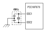 4-MHz resonator is used for the operation clock oscillation by PIC. The precision of this oscillation frequency doesn't influence the precision of the clock. The precision of the clock is decided by the precision of the frequency which is inputted to RB0. Because it doesn't need the high-speed operation of PIC at the circuit this time, 4MHz is used. 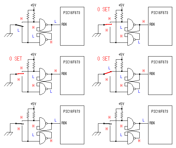 When making a switch ON, the chattering phenomenon which repeats ON/OFF with the point of contact bounding occurs. It is short time that the phenomenon causes. However, because the electronic circuits does high-speed operation, it is the phenomenon which can not be ignored. SR flip-flop circuit is used to prevent from this phenomenon. SR-FF can be made with NAND circuit, too. 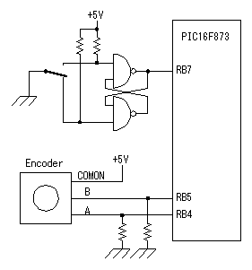 As for the switch to make a time setting mode, a chattering is prevented using SR-FF like the setting of 0 seconds. It shifts to the time setting mode when pushing this switch for 2 seconds continuously. When this switch is pushed in the condition of the time setting mode, the digit to set is shifted. For its purpose chattering prevention is needed. It is possible to prevent if making software to stop detection in a little time after detecting ON. It is terrible work. A rotary encoder is used for the time setting. The rotary encoder which is used this time is mechanical slide type. Two output terminals of the encoder differ in the timing which touches a common terminal by the direction of the turn of the axis. 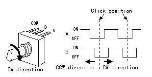 I am introducing this circuit on "Digital dial". 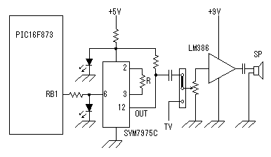 The music by the melody IC sounds as the time signal at every just time ( But eight times on a day ). Because 8 pieces of music are memorized in the melody IC(SVM7975C) which was used this time, it is sounded in another music at 7:00/8:00/9:00/10:00/18:00/19:00/20:00/21:00. In the time except these, I don't sound because it is noisy. Voltage is lowered using the LED because the maximum voltage of SVM7975C is about 3V. When the LED lights up, the voltage of the both edges of the LED is approximately 2V. The speed of the melody can be changed by the resistance(R) which is connected with the 2nd and the 3rd pin. The output of the melody IC is amplified in LM386 and is output from the speaker. This amplifier is generally used to sound a melody but is used for the monitor of the television sound when tuning the channel of the television too. A television signal is used to make a clock synchronize with the precision color burst signal of the TV station. The switching of a source is done with the short pin. At the actual circuit, a switch for the selection of music is put to the 6th pin. It is used when a time and music are shifted. As for the power supply of the melody IC, the battery backed up power is used. In the melody IC, an order with the music to play next is stored. However, an order is initialized when the power stops and the shift occurs to the time and the music. 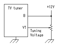 The TV tuner to be using this time is the method which chooses a broadcasting station in the voltage. In the specification, the tuning voltage is from 0V to 28V. However, this time, 12V voltage is used because it is good if one broadcasting station can be chosen. When there is not a broadcasting station which can be chosen at this voltage, it is necessary to make voltage rise. Because the tuning has shifted when there is a voltage change in the power of the tuner, the stable power must be used. 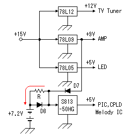 There are four kinds of power supply circuits. They are +12V for the TV tuner, +9V to sound a speaker, +5V to light up LEDs and +5V for PIC, CPLD, melody IC. Among these, a power for PIC, CPLD, melody IC is backed up with the battery. With this, even if commercial power stops the clock can continue operation. Making do the operation only of the basic function of the clock to suppress the consumption of the cell. The battery backed up power is used for the PLL oscillator of the external circuit, too. The TV tuner stops when commercial power stops because it isn't backed up. In the case, the PLL oscillator becomes not synchronous with the color burst of the television signal and a little precision falls. However, if not being a long stop, few influences over the precision occur. As the battery, the chargable Nickel Cadmium battery is used. The voltage of 1 cell is 1.2V. It is used by the series connection in six. So, the voltage which is supplied from the battery when commercial power stops is 7.2V. The 3 terminal regulator which is used for the battery backup power is the regulator that the voltage drop is small. The voltage drop of this regulator is about 0.2V. In case of 78L05, because there is about 1.7V voltage drop, more than 6.7V input voltage is required to get the stable 5V output. In case of this regulator, if there is more than 5.2V input, stable 5V can be output. But, the maximum input voltage of this regulator is 15V, so, it is using the regulator output of 9V as the input for the safety. The regulator output of 12V is to be OK but I am using 9V in the relation of the print pattern. When commercial power is supplied, the battery is charged by 'trickle charging' less than 20mA current. ( red line ) In case of the circuit this time, it is as follows approximately. ( 9V-7.2V )/220ohm =8.2mA As for 'trickle charging', refer to "Charging of the battery". |