PIC PIC
This is PIC16F84A. In case of PIC16F84A, it is possible to use a clock frequency upto 20 MHz. The circuit this time, I am using 10-MHz resonator.
3-to-8 line Decoder ( 74HC138 )
This is the IC which decodes the binary code of 3 bits.
8 conditions can be expressed by 3 bits. 74HC138 outputs only one an L level out of 8 by the 3-bit input condition.
The following table shows correspondence of the input and the output of 74HC138.
| Input | Output |
| C | B | A | 00 | 01 | 02 | 03 | 04 | 05 | 06 | 07 |
| L | L | L | L | H | H | H | H | H | H | H |
| L | L | H | H | L | H | H | H | H | H | H |
| L | H | L | H | H | L | H | H | H | H | H |
| L | H | H | H | H | H | L | H | H | H | H |
| H | L | L | H | H | H | H | L | H | H | H |
| H | L | H | H | H | H | H | H | L | H | H |
| H | H | L | H | H | H | H | H | H | L | H |
| H | H | H | H | H | H | H | H | H | H | L |
|
3 terminal regulator ( 78L05 )
This regulator is used to make the stable power of +5 V.
The maximum output current is 100 mA.
Transistor for the device selection ( 2SA1015 )
These transistors are used to select the device which PIC controls. This is PNP type.
The NPN type can be used, too. In the case, output level becomes opposite. When using PNP type, the transistor becomes ON in L level (0). In case of the NPN type, the transistor becomes ON in H level (1).
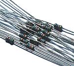
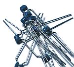
Diode ( 1S1588 )
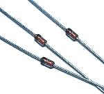
These diodes are used for short circuit prevention of BCD-SW.
IC socket
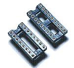
The PIC is mounted after writing a program by programmer. So, the IC socket is necessary.
7 segment LED ( BL9P030.5 )
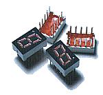
I used small LEDs.
BCD switch
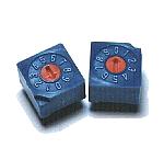
I used a printed board mounting type.
Start/Stop switch
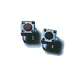
I used switchs with small non lock type for the start and the stop switch.
Output relay ( G5V-1 )
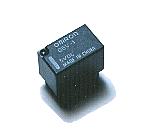
This is the small relay which is made by the OMRON Inc..
 |
| Drive voltage | DC 5V |
| Number of contacts | 1 |
| Contact capacity | 30VDC | 1.0A |
| 125VAC | 0.5A |
| 80VDC | 0.3A |
|
LED for the output display
This is lit up with the operation of the relay to confirm that the circuit works.
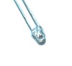
Resonator
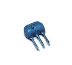
I used 10-MHz resonator. A ceramic vibrator and capacitors for the oscillation are combined inside.
Resistor network
I used the resistor network which four independent resistors were housed in.
Even if you use independent resistors, there is not a problem.
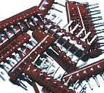
Resistor
I used independent resistors for the part which it isn't possible to use a resistance network for.
It is to be OK at 1/8 W.
Electrolytic capacitor
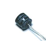
This capacitor is used to be stabilized of the input voltage and to bypass a low frequency noise.
Multilayer ceramic capacitor
These capacitors are used to bypass the high frequency noise of the input and output of the power supply.
Printed board
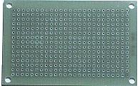
This is an universal printed board with 15 x 25 halls.
Wiring terminal
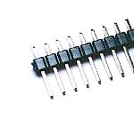
This terminal is used to connect a power supply wire.
Stud
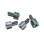
This is used as the leg of the printed board.
|