Circuit explanation for Ultrasonic Range Meter
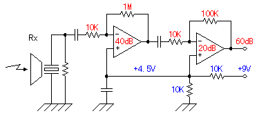 The ultrasonic signal which was received with the reception sensor is amplified by 1000 times(60dB) of voltage with the operational amplifier with two stages. It is 100 times at the first stage (40dB) and 10 times (20dB) at the next stage. The ultrasonic signal which was received with the reception sensor is amplified by 1000 times(60dB) of voltage with the operational amplifier with two stages. It is 100 times at the first stage (40dB) and 10 times (20dB) at the next stage.As for the dB (decibel), refer to "Logarithm Table". Generally, the positive and the negative power supply are used for the operational amplifier. The circuit this time works with the single power supply of +9 V. Therefore, for the positive input of the operational amplifiers, the half of the power supply voltage is appied as the bias voltage. Then the alternating current signal can be amplified on 4.5V central voltage. When using the operational amplifier with the negative feedback, the voltage of the positive input terminal and the voltage of the negative input terminal become equal approximately. This is called virtual grounding. So, by this bias voltage, the side of the positive and the side of the negative of the alternating current signal can be equally amplified. When not using this bias voltage, the distortion causes the alternating current signal. This technique is often used when using the operational amplifier which needs two kinds of powers in the single power. As for the operation of the operational amplifier, refer to "Operation explanation of the triangular wave oscillator". 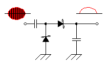 The detection is done to detect the received ultrasonic signal. This is the half-wave rectification circuit with Shottky barrier diodes. The DC voltage according to the level of the detection signal is output to the capacitor behind the diode. The Shottky barrier diodes are used because the high frequency characteristic is good. The detection is done to detect the received ultrasonic signal. This is the half-wave rectification circuit with Shottky barrier diodes. The DC voltage according to the level of the detection signal is output to the capacitor behind the diode. The Shottky barrier diodes are used because the high frequency characteristic is good.As for the Shottky barrier diode, refer to "Diodes". 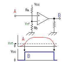 This circuit is the circuit which detects the ultrasonic which returned from the measurement object. The output of the detection circuit is detected using the comparator. At the circuit this time, the operational amplifier of the single power supply is used instead of the comparator. The operational amplifier amplifies and outputs the difference between the positive input and the negative input. This circuit is the circuit which detects the ultrasonic which returned from the measurement object. The output of the detection circuit is detected using the comparator. At the circuit this time, the operational amplifier of the single power supply is used instead of the comparator. The operational amplifier amplifies and outputs the difference between the positive input and the negative input.In case of the operational amplifier which doesn't have the negative feedback, the output becomes the saturation state by a little input voltage. Generally, the operational amplifier has over 10000 times of mu factors. So, when the positive input becomes higher a little than the negative input, the difference is tens of thousands of times amplified and the output becomes the same as the power supply almost.(It is the saturation state) Oppositely, when the positive input becomes lower a little than the negative input, the difference is tens of thousands of times amplified and the output becomes 0 V almost.(It is in the OFF condition) This operation is the same as the operation of the comparator. However, because the inner circuit of the comparator is different from the operational amplifier, the comparator can not be used as the operational amplifier. At the circuit this time, the output of the detection circuit is connected with the positive input of the signal detector and the voltage of the negative input is made constant.
This output is lowered with the resistor to make fit with the input of signal holding circuit (TTL:0V to 5V). 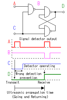 This is the holding circuit of detected signal. SR ( Set and Reset ) flip-flop is used. For the details of SR-FF, refer to "The operation explanation of the D-type flip-flop". The detector is made to be not operate in the constant time(About 1.5 milliseconds) after sending out a transmission pulse to prevent from the wrong detection which is due to the influence of the transmission pulse. This operation is controlled with the software of PIC. When using the capture feature of PIC, this circuit isn't indispensable. Capture operation is done by the change of the capture input in the once. The reason why I am using this circuit is to confirm signal detection operation within the reflected signal detection time(About 65 milliseconds). When sending out next ultrasonic pulse, the output of this circuit is checked. And when the output is L level, an error display is done because the reflected signal could not be detected.  The inverter is used for the drive of the ultrasonic sensor. The two inverters are connected in parallel because of the transmission electric power increase. The phase with the voltage to apply to the positive terminal and the negative terminal of the sensor has been 180 degrees shifted. Because it is cutting the direct current with the capacitor, about twice of voltage of the inverter output are appied to the sensor. The power supply voltage of this drive circuit is +9V. It is converting voltage with the transistor to make control at the operating voltage of PIC(+5V). Because C-MOS inverters are used, it is possible to do ON/OFF at high speed comparatively.  Three 7 segment LEDs are used for 3-digit display. As for the lighting-up of the LED, 1 digit is displayed in the order with the software of PIC. At the circuit this time, I make light up it when the terminal of PIC is L level. So, ANODE COMMON type is used as the LED. The anode common type is the type which the side of the positive(Anode) of the LED is connected inside. It lights up when grounding(L level) a cathode in the segment to want to make light up. As the 7 segment LED, the others have a cathode common type. When you buy them, the specification of the type should be checked.   The sound wave propagation speed in air is changed by the temperature. At 0°C, it is 331.5m/sec. At 40°C, it is 355.5m/sec. The sound wave propagation speed in air is changed by the temperature. At 0°C, it is 331.5m/sec. At 40°C, it is 355.5m/sec.For the details of the propagation speed, refer to "The sound wave propagation speed in the air". This range meter calculates a distance by dividing the propagation time which was measured by the capture feature. I will explain that it does the case of the distance measurement of 1m in the 0°C environment as for the example. The time which the sound wave takes to go and return is 2m/331.5m/sec = 0.006033 seconds = 6.033 milliseconds. The contents of the counter by the capture feature is 6033 within 1 microsecond. For the conversion of this to distance (cm), it divides by 60. It is 6033/60=100.55. The following of the decimal point is cut off. It becomes a measurement error. This conversion value (60) depends on the temperature. It isn't related with the distance to measure. In case of 9 m, it is 54298/60=904.9. The conversion error becomes big when the distance becomes long. This is because it isn't possible to do conversion below the decimal point. In case of 40°C, it is 2m/355.5m/sec = 5625 microseconds and the conversion value is 56. The conversion value should be changed by the ambient temperature. At this range meter, a conversion value is generated using the A/D conversion feature. The A/D converter converts input voltage into the 10-bit digital data. This time, I am using upper 3 bits. So, the A/D conversion result from 0V to 5V is the value from 0 to 7. And 54 is added to this value. Then, the conversion value range is from 54 to 61.  I used 4-MHz resonator. I used 4 MHz in the relation of the timer in the count time. When using 4-MHz clock, it is 1 microsecond per count for the counter count up time. Timer1 to use for capture is a maximum of 65535 counts(16 bits). So, a maximum of 65.535 milliseconds count is made. The propagation speed of the sound in air is 343 m/second in case of 20°C. In the time which goes and returns in the 10-m distance, it is 20m/343m/sec = 0.0583 seconds (58.3 milliseconds). As the range meter this time, it is an exactly good value. 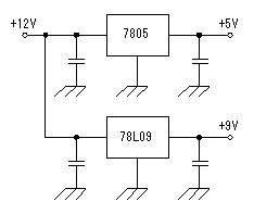 The voltage of +5V and +9V are made with +12V power supply using the 3 terminal regulator. +9V are used for the transmitter and the receiver. 100-mA type is used because few needed electric currents. In other circuit, +5V is used. +5V voltage is used for the lighting-up of LEDs, because they are controlled by PIC. The about 10-mA electric current per segment flows through the LED. So, it becomes about 80 mA when all segments(eight) light up. Because few electric currents of the other IC occur, I think that you can use a 100-mA type, too. I used a 1A type for the safety. |