Parts explanation of signboard 2
 This is PIC16F84A. In case of PIC16F84A, it is possible to use a clock frequency upto 20 MHz. The circuit which I am introducing, 10-MHz resonator is used.  The latch register function for the LED is made to have by this CPLD. For latching 112 LEDs, two CPLDs are used. As for the logic of this CPLD, refer to "7bits x 16rows Latch Register for Signboard".  The 5 binary counter is used to shift the display of the LED (green) for the ornament to have installed around the display part of the signboard. As for the logic of this CPLD, refer to "5bits LED Shifter for Signboard".  This IC generates the clock pulse for the 5 binary counter. This time, I used CMOS-type TLC555.  This IC is the switching regulator which outputs stable voltage of +5V. This is a 1-A type. 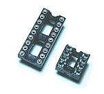 These are the socket to mount PIC and TLC555.  These are the socket to mount CPLD. 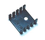 Because there are few the inner loss of the switching regulator, it doesn't need big heat sink. This time, the a maximum of 1-W loss coming-out. So, I used a small heat sink. 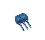 I used 10-MHz resonator. A ceramic vibrator and capacitors for the oscillation are combined inside. 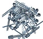 High brightness type LEDs of red are used for the data display part. LEDs of green are used for the edge part. Any LED has a 5-mm diameter with the transparent color type. 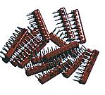 This is the resistor to control an LED current of the display part. Four independent resistors are housed in one resistor network. 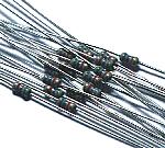 For the current control of the edge LED, 1/8-W resistor is used. 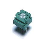 This resistor is used to adjust the shifting speed of the edge LEDs. 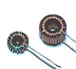 These are the coil for switching regulator. As for the outline of the toroidal coil, refer to toroidal coill. 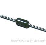 This is the diode to use with the switching regulator. In case of LM2575, the switching frequency is about 52 KHz. So, it isn't possible to use usual rectifier diode because the oppositely recovery time is long. As for the outline of the Shottky barrier diode, refer to Shottky barrier diode. 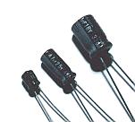 The electrolytic capacitors are used for 555 oscillator and the switching regulator. You should use the capacitor with few ESR(Equivalent Series Resistance) for the ripple filter of the switching regulator. The capacitor has the inductance and the resistance as well as the capacitance. This resistance is called ESR. When the value of ESR is big, the hear is generated with the electric current which flows through the capacitor. Comparatively big electric current flows through the capacitor for ripple filter of the switching regulator. So, the capacitor which has low ESR should be used. 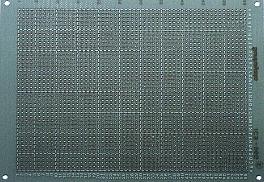 This is an universal printed board with 40 x 55 halls. 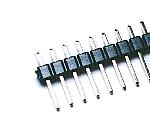 This terminal is used to connect a power supply wire. 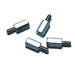 I made LED display unit and control unit separately. Those printed boards are connected with these studs. I used the stud with 10-mm length. 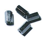 This stud is used to put the unit on an acrylic board. I used the stud with 10-mm length. 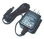 This is the adapter which changes AC100V into DC12V. The switching regulator is used for this adapter. The capacity of this adapter is 1A type. 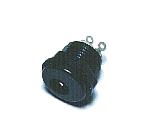 This is the connector to connect AC adapter. 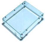 I made a simple acrylic cover for the equipment.  LEDs are mounted on the printed board through black paper. Because, the lighting-up of the LED is easy to see. |