 Correction of the pattern Correction of the pattern
 It sometimes happens to correct a part of the pattern drawn manually or automatically. There is a way of rewiring manually after returning to the condition before wiring using Ripup. Here, I introduce the way of correcting to use Move and Split. The pattern can be corrected dividing one pattern into two with Split. It is useful when bending a straight line pattern. In the way of introducing here, the position of the pattern can be corrected but can not change thickness(width). When changing thickness, it makes a condition before wiring using Ripup and it is necessary to wire manually. It sometimes happens to correct a part of the pattern drawn manually or automatically. There is a way of rewiring manually after returning to the condition before wiring using Ripup. Here, I introduce the way of correcting to use Move and Split. The pattern can be corrected dividing one pattern into two with Split. It is useful when bending a straight line pattern. In the way of introducing here, the position of the pattern can be corrected but can not change thickness(width). When changing thickness, it makes a condition before wiring using Ripup and it is necessary to wire manually.
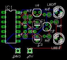
I will explain with the circuit which is used on "Let's try".
The correction part is the pattern of the 7th pin of the IC1 and GND terminal.
As for the figure on the left, Show icon is used for that it is easy to see.

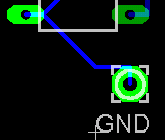
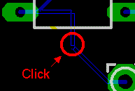
First, it corrects wiring on the GND terminal using Move.
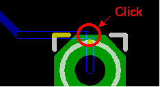 |
It clicks the pattern to correct after pushing Move icon. By this, the displaying of the pattern which can move changes to the line only of the bordering. |
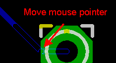 |
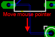
Wiring is transformed as the mouse moves.
It isn't necessary to push the left button of the mouse continuously.
In case of the example on the left, it is moving a mouse pointer to the lower left. |
 |
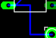
It clicks the left button of the mouse if a position is fixed.
As for the figure on the left, Show icon is used for that it is easy to see. |

Next, it bends wiring with Split.
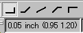 |
The bend angle can be selected with the bend angle icon which is displayed at the top of the board window.
From left
 0 : Starting point - horizontal - vertical - end 0 : Starting point - horizontal - vertical - end
1 : Starting point - horizontal - 45° - end
2 : Starting point - end (straight connection)
3 : Starting point - 45° - horizontal - end
4 : Starting point - vertical - horizontal - end
The figure under the bending angle icon is a grid interval. The bending position of the line is the point of intersection of the grid. A grid isn't displayed on the screen.
The grid interval can be changed by View -> Grid.
The figure in ( ) shows the position of the pointer. The starting point is the + mark which is at the lower left. |
 |
It clicks the part to want to bend after pushing Split icon. The bending angle is due to the contents of the icon to have been explained above. In case of this example, "0" is used.
At first, I think that it bends as different from the angle that you want to bend. Try with the variety and catch a know-how. |
 |
Wiring is transformed as the mouse moves.
In case of this example, it is moving a mouse pointer to down.
It isn't necessary to push the left button of the mouse continuously. |
 |
It clicks the left button of the mouse if a position is fixed.
As for the figure on the left, Show icon is used for that it is easy to see. |
|