On this page, I will introduce a way of using the CPLD development tool( Project Navigator ) of the Xilinx Inc. using the simple model.
This tool is equipped with the various functions but that I introduce here is only a minimum function.
The person who doesn't understand a way of using at all refer to this page.
The use language is VHDL. As for VHDL, refer to "Development language specification ( VHDL )".
The version of the tools when I am making this page is hereinafter.
| Project Navigator: |
Release Version: WebPACK 3.1WP1.x
Application Version: build+D-20+0 |
| JTAG Programmer: |
Release Version: WebPACK 3.1WP1.x
Application Version: D.20 |

 Sample circuit Sample circuit
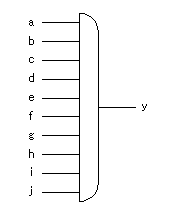
I attempt to design a 10 input AND circuit for practice.

 Start-up of Xilinx Project Navigator Start-up of Xilinx Project Navigator
First, start up "Xilinx Project Navigator".
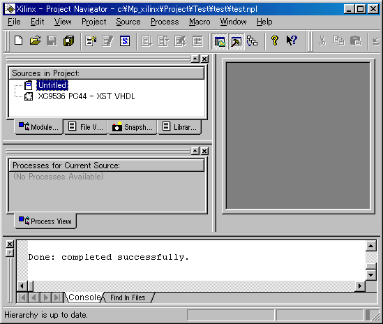
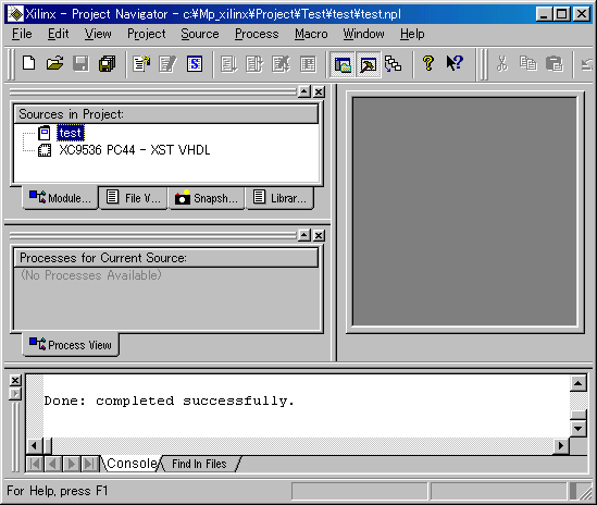
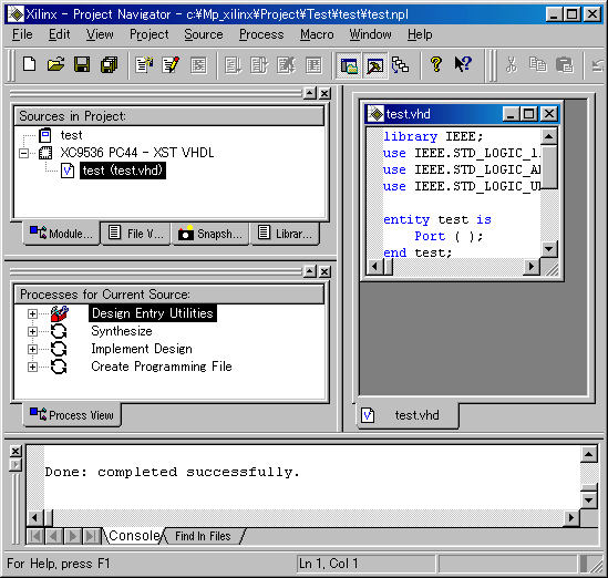
The following window will be displayed.
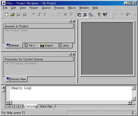
Sources in Project is the window to display a device name, a source module name and so on.
Processes for Current Source is the window to display a various function menu.
The window on the right( HDL Editor workspace window ) is the window to display a source code.
The window most below( Transcript window ) is the window to display the log of the processing elapse. |

 Making of a project Making of a project
On this tool, a way of work management by the project is adopted.
By making a project, it is possible to have a series of design work of CPLD by the navigator.
 The making of a folder for the project The making of a folder for the project
The after management is easy when making the folder which stores files of the project before beginning work. I made a folder which stores the related files of the test project as C:\MP_xilinx\Project\Test\test.
 The making of a project The making of a project
The new project can be made with the following procedure.
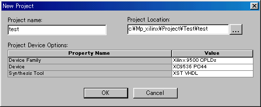
When select File -> New Project , the dialog of the project creation of file is displayed.
A project name, the place which saves a project, the kind of the device and the language to use and so on are set by this dialog. Click Value of the device and the language to use and choose the contents which fit in from the displayed pull-down menu.
Sources in Project of Project Navigator changes as follows when the registration of the project is done.
 The registration of the project title The registration of the project title
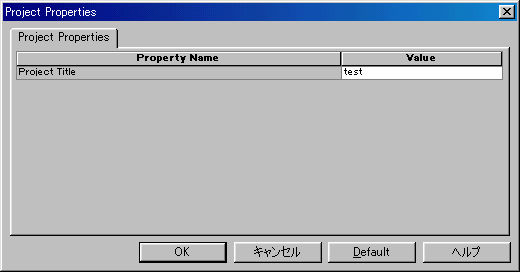
Next, you give the title of the project.
The registration dialog of the title is displayed when choosing Source -> Properties or double-clicking  . .
The project title of Sources in Project changes to the set title.

 Making of a source file Making of a source file
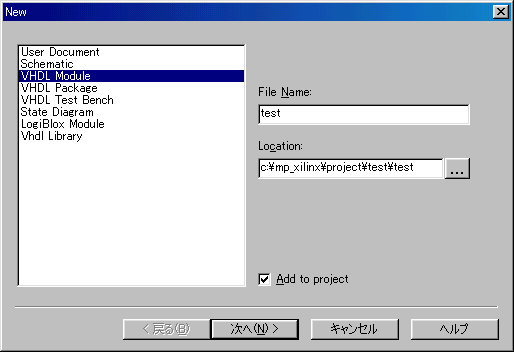
A source type selection dialog is displayed when choosing Source -> New or clicking the  button. button.
Select "VHDL Module" from the displayed item. When using a language except VHDL, select a corresponding language.
Type "File Name", and confirm the file saving path of "Location" and click "Next".
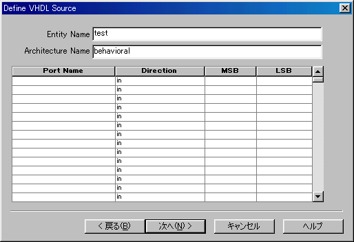
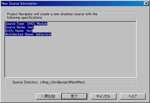
Type "Entity Name" and "Architecture Name". The ports can be specified by this dialog. However, in the example this time because it specifies by the description of VHDL from behind, click "Next" without input the ports. Following confirmation screen is displayed. Click "Finish" if there is not mistake in the contents.
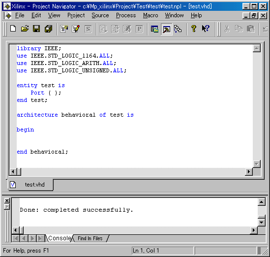
The window (HDL Editor window) of the source code is displayed in HDL Editor workspace window of Project Navigator.
Display or non-display of each window can be controlled with the View menu.
Try that the window changes how by each item.
To spread a source code window, it clicks Project Workspace of the View menu and it removes checking. You can expand by clicking  , too. To make display a source code window in whole HDL Editor workspace window, it clicks the window maximization button in the upper right like usual window control. , too. To make display a source code window in whole HDL Editor workspace window, it clicks the window maximization button in the upper right like usual window control.
When wanting to return to the origin, it operates Window menu.
The basic part of the format of VHDL is already written in the displayed source code window.
I omit a detailed explanation. The contents of the outline are hereinafter.
The blue character shows the character of the format which is prescribed in VHDL.
library IEEE; |  | IIt specifies to use the VHDL library which is prescribed by the IEEE. |
 |
use IEEE.STD_LOGIC_1164.ALL; |
| It specifies to use all of the std_logic libraries which are prescribed in IEEE 1164. |
use IEEE.STD_LOGIC_ARITH.ALL; |
| It specifies to use all of the Arithmetic libraries which are prescribed in IEEE. |
use IEEE.STD_STD_LOGIC_UNSIGNED.ALL; |
| It specifies to use all of the Unsigned arithmetic libraries which are prescribed in IEEE. |
 |
entity test is
    Port ( );

end test; |
|
This is the column which the entity to specify by the test file is described in.
A port sentence, a generic sentence are written. |
 |
architecture behavioral of test is
begin

end behavioral; |
| This is the column which logic specification with the function to make CPLD have is described in. |
|
This time, I added the following to entuty and architecture to make one 10 input AND circuit. The red is an addition part.
library IEEE;
use IEEE.STD_LOGIC_1164.ALL;
use IEEE.STD_LOGIC_ARITH.ALL;
use IEEE.STD_STD_LOGIC_UNSIGNED.ALL;

entity test is

  port (
    a,b,c,d,e,f,g,h,i,j : in  std_logic;
    y                   : out std_logic);

end test;

architecture behavioral of test is
begin

  y <= a and b and c and d and e and f and g and h and i and j;

end behavioral; |
After doing above-mentioned change, save a file by File -> Save or by the  button. button.

 Syntax check Syntax check
By the following operation, the normality of the format (the grammar) of the made source file is confirmed.
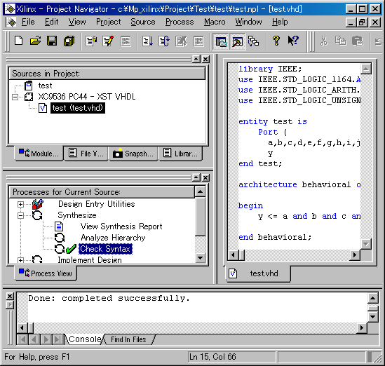
Double-click "Check Syntax" which is displayed in the Process for Current Source window.
This has the checking of format (Syntax).
If the checking result is to be OK, Check Syntax has a green checking mark.
Also, "Done: completed successfully." is displayed in the end of the situation display window.
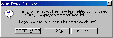
When checking a format without saving a file, the following dialog which shows that a file isn't saved is displayed. It is saved if clicking "Yes".
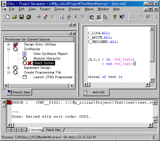
I attempt to make an intentional error occur as the example.
I delete the last semicolon(;) of the port declaration of entity and I attempt to execute Check Syntax.
Check Syntax has a red X mark.
Also, "Done: failed with exit code: 0001." is displayed in the end of the situation display window.
The position of the error can be known with the situation display window.
 ERROR : (VHP__0162). C:\MP_xilinx\Project\Test\test\test.vhd Line 10. Read symbol END, expecting ';'. ERROR : (VHP__0162). C:\MP_xilinx\Project\Test\test\test.vhd Line 10. Read symbol END, expecting ';'.
An error is detected at the 10th line and to have become END in the condition which doesn't have semicolon (;) is displayed.
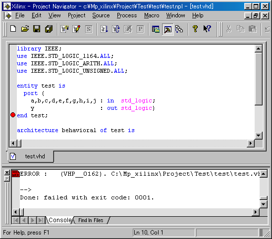
When double-clicking  , the mark which shows an error on the left side of the source code is displayed. , the mark which shows an error on the left side of the source code is displayed.
Because the mark shows the line which detected an error. So, check previous lines so on.
The error mark doesn't disappear even if it corrects an error and becomes OK. To erase the error mark, after closing a source code window once by File -> Close, and display it again by double-click a source file in Sources in Project.

 Fitting Fitting
It makes a file for CPLD from the source file by this processing. In the software, it calls this processing compilation. By this tool, it is called a fitting. I think that it means to make the object which fits hardware.
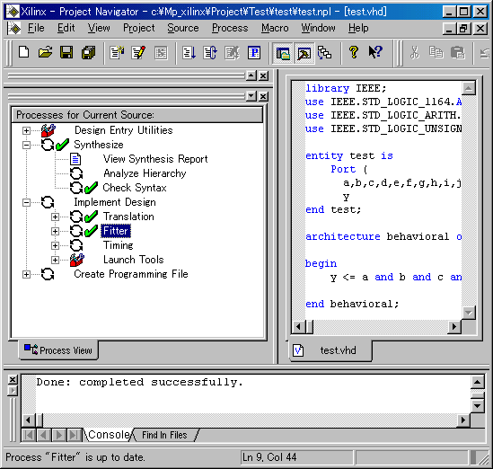
Double-click "Fitter" which is displayed at the Process for Current Source window.
The fitting processing begins with this operation.
The progress situation of the processing is displayed in the status graph with window tail.
Fit Design has a green checking mark if the fitting result is to be OK.
Also, "Done: completed successfully." is displayed in the end of the situation display window.
 The confirmation of the fitting result The confirmation of the fitting result
In case of the complicated circuit, the various data must be confirmed. This time, I confirm the situation of the assigned pin.
Double-click Fitter Report which is displayed in the Process for Current Source window.
A report window is displayed. There is following figure in it.
This figure shows the assignment of the pin. Because it isn't fixing a pin this time, the tool is selecting a pin automatically. So, the row of the pins isn't beautiful.
****************************  Device Pin Out ****************************

Device : XC9536-5-PC44


      T  T  T     T  T  T  T  T  V  T
      I  I  I     I  I  I  I  I  C  I
      E  E  E  y  E  E  E  E  E  C  E
      --------------------------------
     /6  5  4  3  2  1  44 43 42 41 40 \
TIE | 7                             39 | TIE
  i | 8                             38 | h
  a | 9                             37 | e
GND | 10                            36 | c
  b | 11         XC9536-5-PC44      35 | d
  j | 12                            34 | f
  g | 13                            33 | TIE
TIE | 14                            32 | VCC
TDI | 15                            31 | GND
TMS | 16                            30 | TDO
TCK | 17                            29 | TIE
    \ 18 19 20 21 22 23 24 25 26 27 28 /
      --------------------------------
      T  T  T  V  T  G  T  T  T  T  T
      I  I  I  C  I  N  I  I  I  I  I
E E E C E D E E E E E |
By this figure, you find that from the "a" port to the "j" port are allocated respectively in 9,11,36,35,37,34,13,38,8,12 and "y" port is allocated in the 3rd pin.
This could have done the preparation of the data to write in CLPD.

 Programmer start-up Programmer start-up
The operation after this is the work to do after connecting a personal computer and CPLD device with the download cable. I attempt to start up a programmer for the practice.
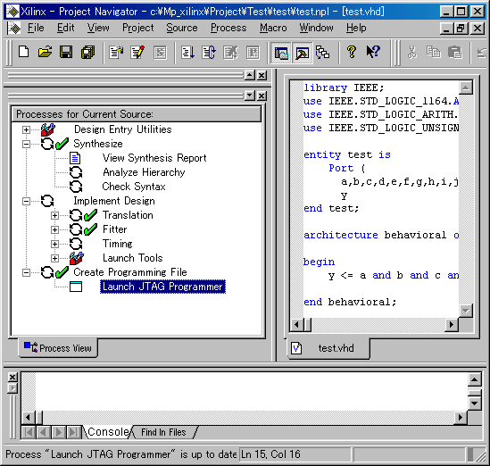
Double-click "Launch JTAG Programmer" which is displayed at the Process for Current Source window.
JEDEC file(Extension : JED) for the writing to CPLD is made and the window of JTAG Programmer is displayed.
 The window of JTAG Programmer is shown below.
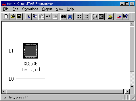
When using the parallel port(DSUB25) of the PC, it specifies Parallel by Output -> Cable Setup -> Cable Communication Setup. Data is transferred to CPLD if pushing the OK button.
When a cable isn't connected, it becomes an error.
As for the actual programming operation, refer to "How to use CPLD programmer".
 |
