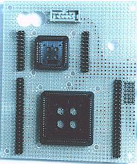
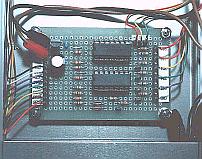
PLCC socket assembly PLCC socket assembly
The sockets for 44 pins, 84 pins and for the outside JTAG are mounted on the universal printed board. The printed board which mounted sockets is put to the lid of the case. As for the position of the sockets, the operation of the screwdriver must be considered when removing a device.
Installation of the rotary switch
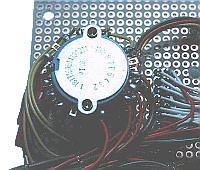
I considered the operability of the switch and I put the switch on the upper right of the case.
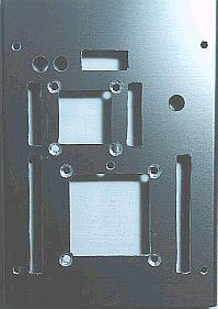
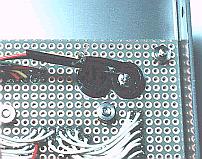
Installation of the printed board for the socket
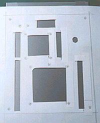
As the procedure which is installed a printed board on the lid of the case, it puts marks to the position of the sockets and makes holes on the lid of the case using the handsaw and the files so on.
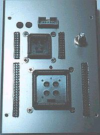
When attaching a device to the PLCC socket, power is gained to the printed board. To prevent from the damaging of a printed board by this power, I fixed on the position of the four corners of the socket with the case using the plate screw. The screws are hidden behind the panel.
Installation of the DSUB-25 connector
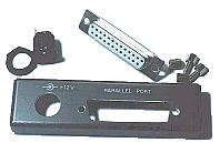
DSUB-25 connector is installed on the back of the equipment. The form of the connector isn't square. I made a hole which is smaller a little than the connector with the handsaw and shaved to the size of the connector with the file.
Installation of the control unit
This unit is installed in the position which doesn't touch a rotary switch.
Installation of the LED
It is installed in the position where the display is easy to see.
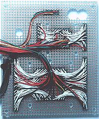
JTAG cable
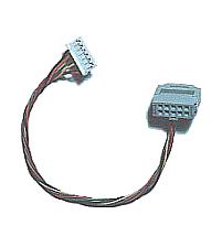
This is the cable to write data in CPLD to have mounted on the printed board.
 |