
 Control Unit Control Unit

This unit is composed of the bus buffer circuit and the power circuit for the JTAG signal.
PLCC socket
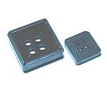
The sockets for 44 pins and 84 pins are mounted on the unit. I want zero pressure type like the PIC programmer. However, it can not be realized by the structure of the socket.
To remove a device from the socket is a little complicated.
DSUB-25 connector ( Female )
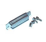
This is the connector to connect the cable of the personal computer.
As for the connector of the cable which was used this time, the both edges were to do male connector being. Therefore, the connector of the female is used for the side of the programmer.
Cable for DSUB-25
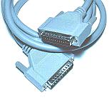
This is the cable that the both edges had a male connector. The cable which all of the 25 pins are connected with should be used for this cable. When using a cable for the modem, it should use a straight cable. It is not a crossing cable.
Case
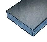
I used an aluminum case.
The size of the case has 100-mm width, 30-mm height, 140-mm depth.
Rotary switch
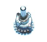
This switch is used for ON/OFF of the power and switching of 44 pins, 84 pins, the outside JTAG. The selection of either of 44 pins, 84 pins or the outside JTAG by this switch. A 6 circuit -4 contact type is used.
Knob
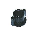
As the knob of the switch, the type for which the position of the switch is easy to see is used.
LED for the programming display
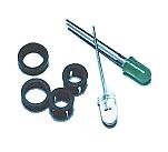
The green LED lights up when turned on. The white LED(The lighting-up color is red) blinks when writing data in the CPLD device.
Outside JTAG cable connector
This connector is used to connect with the CPLD device which is mounted on the printed board outside.
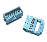
Connector of JTAG of the side of the printed board
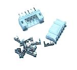
This is the connector to mount on the printed board outside. A shape isn't decided. I used the connector which is as small as possible to make implementing space little.
Generally, I write data in CPLD using the programmer. So, I don't put a connector to the printed board outside.
Power connector
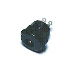
The inputting voltage of the unit is +12 V. The inner circuit works at +5 V using the regulator.
AC adapter
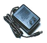
This device changes to DC 12V from AC 100V.
Front panel
The panel which was printed with the color printer is put to the surface of the programmer.
I put in printed paper with the acrylic board with 0.5-mm thickness.
Terminal
This is the terminal to confirm CPLD in the operation. All PLCC pins are connected with the terminal.
|