DC/AC inverter (1)
 |
|
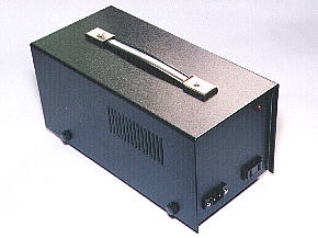
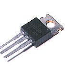
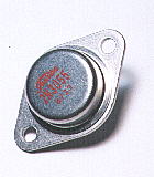
This is the circuit which outputs 100 V of the alternating current from the input of 12 V of the direct current. It is convenient to use the equipment which works in the alternating current using the battery (DC12V) of the car. It is using the IC-type multi-vibrator for the oscillator of the alternating current. The frequency is about 60 Hz. I used 7400 as the IC for the oscillator but 7404 is OK. The signal of the oscillator has the switching operation with TR1-TR4. TR2 and TR4 are the transistor for the main switching. Because these transistors are difficult to drive directly from the IC, they make amplify in the electric current using TR1 and TR3. The connection between TR1 and TR2, and TR3 and TR4 connects in the way of being called "the Darlington connection". The transformer that the input is 100 V and the output is 24 V in the one with the 12 V center tap makes the input and the output opposite and uses. Because the comparatively big electric current (about 3 A) flows through the part of the line that the circuit diagram is bold, the thick wiring materials are used. The output voltage is the square wave ( Depending on the equipment, there is one which can not be used. When the load is added, the wave form of the output voltage changes by the inductance of the transformer. I was asked about 220V output from some readers. The output voltage of the inverter is decided only in the transformer. You can use the transformer with 220V as for primary(input) and 12V as for secondary(output). At my circuit, primary and secondary should be used oppositely. Then, you will be able to get AC220V from DC12V.
|
||||||||||||||||||||||||||||||||||||||