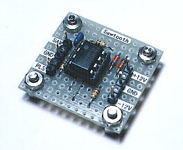
Sawtooth wave oscillator
 |
 |
|
In this page, I introduce the sawtooth wave oscillator which used the operational amplifier (TL082). The composition of this circuit is the same as the triangular wave oscillator basically and is using two operational amplifiers. At the circuit diagram above, IC(1/2) is the Schmitt circuit and IC(2/2) is the integration circuit. The difference with the triangular wave oscillator is to be changing the time of the charging and the discharging of the capacitor. When the output of IC(1/2) is positive voltage, it charges rapidly by the small resistance(R1) value.(When the integration output voltage falls) When the output of IC(1/2) is negative voltage, it is made to charge gradually at the big resistance(R2) value. The output waveform of the integration circuit becomes a form like the tooth of the saw. Such voltage is used for the control of the electron beam (the scanning line) of the television, too. When picturing a picture at the cathode-ray tube, an electron beam is moved comparative slow.(When the electron beam moves from the left to the right on the screen) When turning back, it is rapidly moved.(When moving from the right to the left) Like the triangular wave oscillator, the line voltage needs both of the positive power supply and the negative power supply. Also, to work in the oscillation, the condition of R3>R4 is necessary. However, when making the value of R4 small compared with R3, the output voltage becomes small. The near value is good for R3 and R4. You may make opposite if not oscillating using the resistor with the same value. The circuit diagram above is using the resistor with the value which is different to make oscillate surely. The oscillation frequency can be calculated by the following formula.
When calculating at the value which is shown with the circuit diagram, the oscillation frequency is as follows.
The oscillation frequency in the circuit which was made this time was to 40 Hz be.
|