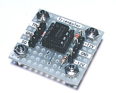
Triangular wave oscillator
 |
 |
|
In this page, I introduce the triangular wave oscillator which used the Operational Amplifiers (TL082). The circuit uses the two OP amplifiers. The OP of the one works as "the Schmitt circuit". The other OP works as "the integration circuit". At the circuit diagram above, IC(1/2) is the Schmitt circuit and IC(2/2) is the integration circuit. The output of the Schmitt circuit becomes the square wave. The output of the Schmitt circuit is inputted to the integration circuit. The output of the integration circuit becomes the triangular wave. The power supply needs both of the positive power supply and the negative power supply. Also, to work in the oscillation, the condition of R2>R3 is necessary. However, when making the value of R3 small compared with R2, the output voltage becomes small. The near value is good for R2 and R3. You may make opposite if not oscillating using the resistor with the same value. The circuit diagram above is using the resistor with the value which is different to make oscillate surely. The oscillation frequency can be calculated by the following formula.
When calculating at the value which is shown with the circuit diagram, the oscillation frequency is as follows.
The oscillation frequency in the circuit which was made this time was to 1130 Hz be.
|