Also: Espressif ESP-32 System On Chip +
Designed and originally made by Espressif in China, it's a VERY low cost (e.g. $5USD) WiFi IPv4 connected embedded controller with a few pins of GPIO, UART, I2C, 10 bit ADC, SPI, PWM, internal temp, etc.. on a 11.5mm x 11.5mm "SoC", perfect for Internet of Things
Out of the box, they have an "AT" command set so a device connected to the UART can tell them to connect to the network, and send and recieve data. They are typically used, in this mode, with some other embedded device. However, a GNU (GCC) based toolchain has been developed ^ which allows them to be re-programmed for complete applications in a single module. And new firmware packages are being developed, such as a small LUA interpreter ^ These packages are fairly easy to install via a built in bootloader by connecting the UART to a PC (USB to 3.3v serial adapter), holding a GPIO pin down with a low value resistor (usually pin 0), restarting the module, and then downloading the .bin file. Of greatest interest to the hobbiest, is it's compatibility with the Arduino IDE^. In the Arduino IDE, go to File / Preferences, and under "Additional Boards Manager URLs:" add "http://arduino.esp8266.com/stable/package_esp8266com_index.json". Then under Tools / Boards / Boards Manager, and filter by ESP8266 and install the support files.
Don't even try to program an ESP-8266 module that wasn't made by AI-THINKER. The knock offs will NOT work correctly.
https://cdn-shop.adafruit.com/product-files/2471/0A-ESP8266__Datasheet__EN_v4.3.pdf Datasheet.
Processor: Tensilica^ Xtensa LX3^ processor 106micro Diamond Standard core. 32-bit RISC. Runs at 80 MHz but can go up to 160 MHz, it has ~80kB DRAM (Data RAM), and ~35kB of high speed IRAM (Instruction RAM). 64K ROM. Support required: 4 capacitors, a crystal and an external flash (which are all on the ESP-8266 modules).
Integrated WiFi 2.4 GHz, WPA/WPA2, 802.11 b/g/n protocol. +20dBm in
b mode, STBC, 1x1 MIMO, 2x1 MIMO, A-MPDU & A-MSDU frame aggregation &
0.4µs guard interval. Integrated TR switch, balun, LNA, power amplifier
and matching network. Wake up and transmit packets in < 2ms. MQTT is
recommended as a lightweight but robust network messaging system:
https://github.com/tuanpmt/esp_mqtt#esp_mqtt
Note: NONE of the versions prior to the ESP-12 are actually FCC approved, even if they have the FCC logo. ESP-12 has ID: 2ADUIESP-12 and CE: BCTC-141212468
Firmware ROM impliments (see file eagle.rom.addr.v6.ld from SDK): MD5 (w/hmac), SHA1, comms with the external flash/memory commands, SDIO 2.0, SPI, UART functions, software floating point, AES, printf, low-level IO tools, real-time event scheduler, 802.11b/n/g, TCP/IP IPv4, WPA/WPA2.
External FLASH is normally Winbond W25Q40BVNIG SPI for 512KB. Some versions have more, e.g. EFP-12 and OLIMEX
IO is somewhat limited on early modules, but later modules increase the number of available pins. Note 3.3v levels; use of 5 volts anywere will damange the unit. Level conversion required.
Power requirements: 3.3v, Deep sleep power <10uA, Power down leakage
current < 5uA, Standby < 1.0mW (DTIM3),
^
^
Standard operation 70 to 80mA with 300mA peaks of 1mS or less. At full CPU
load and transmitting, may need up to 300mA peak.
https://www.youtube.com/watch?v=6SdyImetbp8
Waking up from sleep mode takes about 16mA — then about 3 seconds to reconnect via DHCP, precious time at 70mA. Using a static IP address you can pare that down to half a second.
All new code loaded via bootloader. Reset with GPIO 0 pulled to ground with
a low value
resistor^,
"ready" will be transmitted at one of 9600,115200,57600, or, most often,
76800 baud. In the bootup message 'boot mode:(x,y)' three low bits of x are
{GPIO15 aka MTDO, GPIO0, GPIO2}. If GPIO15 is high, it will wait for an SD
card. If GPIO0 is high, it will boot from flash, if low, will enter the
bootloader. In any case, GPIO2 is expected to be high
(floating).^
^
e.g. boot mode:(1,6)' is what you want to see for programming mode. A simple
circuit like this can help:
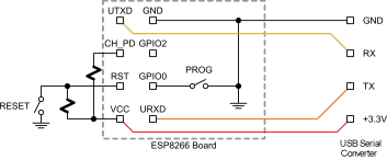 Programming checklist
Note: You can use the serial adapter and reset circuit on a NodeMCU to program an ESP-01 or other simpler module. Just disable the nodemcu module by setting en to ground. Then run 3v3, ground, tx, rx, gpio0, and reset to your esp01. Pull En high on esp01. Program. Video^.
Versions / Modules
| Board ID | pins | pitch | form factor | LEDs | Antenna | Ant.Socket | Shielded | dimensions mm | FLASH | |
|---|---|---|---|---|---|---|---|---|---|---|
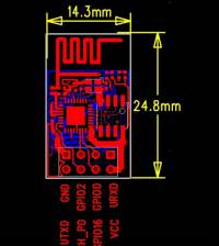
| ESP-01 | 8 pinout | .1“ | 2×4 DIL | Yes | Etched-on PCB | No | No | 14.3 x 24.8 | ||
| ESP-02 | 8 | .1” | 2×4 notch | No? | None | Yes | No | 14.2 x 14.2 | ||
| ESP-03 | 14 | 2mm | 2×7 notch | No | Ceramic | No | No | 17.3 x 12.1 | ||
| ESP-04 | 14 | 2mm | 2×4 notch | No? | None | No | No | 14.7 x 12.1 | ||
| ESP-05 | 5 | .1“ | 1×5 SIL | No | None | Yes | No | 14.2 x 14.2 | ||
| ESP-06 | 12+GND | misc | 4×3 dice | No | None | No | Yes | ? | ||
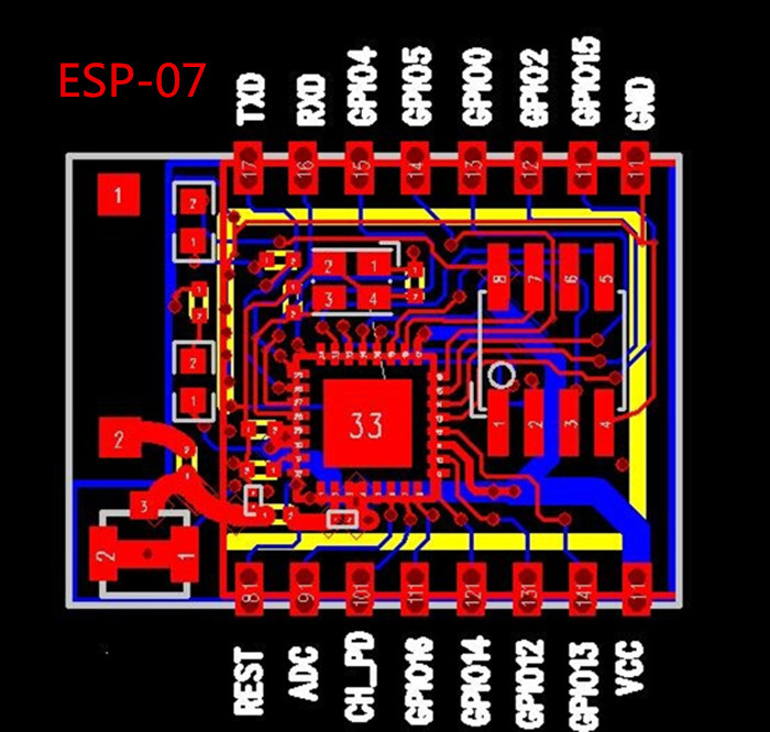
| ESP-07 | 16 pinout | 2mm | 2×8 pinhole | Yes | Ceramic | Yes | Yes | 20.0 x 16.0 | ||
| ESP-08 | 14 | 2mm | 2×7 notch | No | None | No | Yes | 17.0 x 16.0 | ||
| ESP-09 | 12+GND | misc | 4×3 dice | No | None | No | No | 10.0 x 10.0 | ||
| ESP-10 | 5 | 2mmm? | 1×5 notch | No | None | No | No | 14.2 x 10.0 | ||
| ESP-11 | 8 | 1.27mm | 1×8 pinhole | No? | Ceramic | No | No | 17.3 x 12.1 | ||
| ESP-12 | 16 | 2mm | 2×8 notch | Yes | Etched-on PCB | No | Yes | 24.0 x 16.0 | 4MB | |
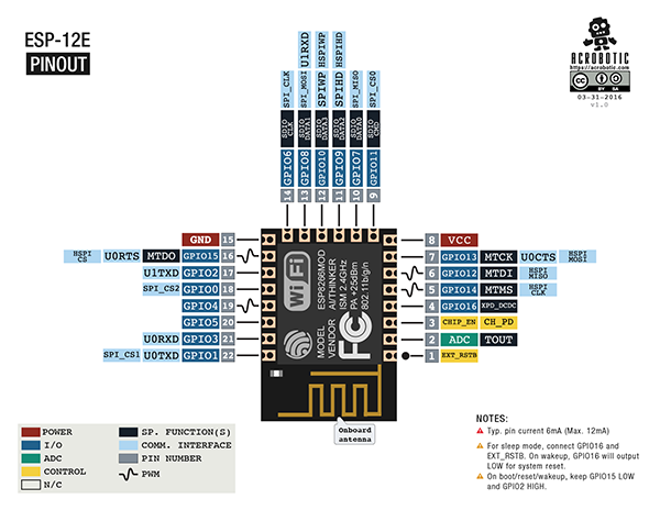
| ESP-12-E | 22 pinout | 2mm | 2×8 notch | Yes | Etched-on PCB | No | Yes | 24.0 x 16.0 | ||
| ESP-13 | 18 | 0.8mm | ? notch | ? | Etched-on PCB | ? | ? | ? x ? | ||
| Olimex | 22 | .1" | Yes | Etched-on PCB | No | No | 2MB | |||
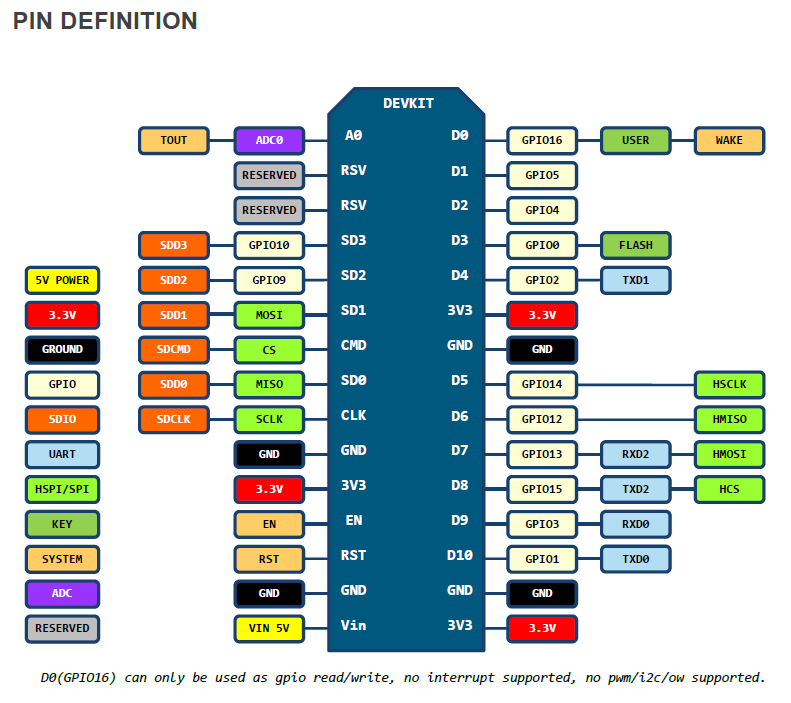
| NodeMCU^ | 16 pinout | .1" | DIP 0.8" | Yes | Etched-on PCB | No | No | 48.3x25.4 1.9x1" | ||
1. On some ESP-12E modules, GPIO4/D2 and GPIO5/D1 are labeled incorrectly.
https://github.com/esp8266/Arduino/issues/437
https://www.esp8266.com/viewtopic.php?f=5&t=3163
Setting analogWrite range and frequency: analogWriteRange(new_range) sets the upper limit of the values to be sent via analogWrite. Call analogWriteFreq(new_frequency) to change the frequency. PWM frequency is 1kHz by default. Note: This is specific to ESP (not part of standard Arduino)
Print MAC address: Can be important if max address filtering is used on the local wifi:
uint8_t MAC_array[6];
char MAC_char[18];
sprintf(MAC_char,"\n\rMAC ");
    WiFi.macAddress(MAC_array);
    for (int i = 0; i < sizeof(MAC_array); ++i){
      sprintf(MAC_char,"%s%02X:",MAC_char,MAC_array[i]);
    }
Deep sleep (restarts in setup, just as if power had failed)
ESP.deepSleep(sleepTimeInSeconds * 1000000, RFMode mode = RF_DEFAULT));
`mode` is one of `WAKE_RF_DEFAULT`, `WAKE_RFCAL`, `WAKE_NO_RFCAL`,
`WAKE_RF_DISABLED`.
(GPIO16 needs to be tied to RST to wake from deepSleep.)
Automatic Reconnect On Wake-Up, is the default. So even before you Wifi.begin, if you were connected before, you suddenly will be again. If that isn't what you want:
WiFi.persistent(false);
WiFi.mode(WIFI_OFF);
WiFi.mode(WIFI_STA);
WiFi.begin(ssid, password);
Avoiding the Bootup
Garbage. On startup, the unit will send out a string
of data about version, etc... at a strange baud rate, 76,4884. There is no
way to disable this. Instead, connect a serial device to the alternate TX
and RX pins. Serial uses UART0, which is mapped to pins GPIO1 (TX) and GPIO3
(RX). Serial may be remapped to GPIO15 (TX) and GPIO13 (RX) by calling
Serial.swap() after Serial.begin. Calling swap again maps UART0 back to GPIO1
and GPIO3. Use Serial.flush() to block until serial sending is finished before
swapping.
https://github.com/esp8266/Arduino/blob/master/doc/reference.md#serial
Xon/Xoff because no interrupt for serial recieved data is supported on the ESP in the Arduino environment, we must check for incomming data when we want to write data, and hold off if we get an Xoff. We can't avoid taking other characters out of the recieve buffer, becase the Xoff could be "hiding" behind one of them. So we MUST receive all characters sent while we are waiting to send, which means we must buffer those characters into our own rxbuf. So the standard get and put character routines must incorporate that fact.
boolean xoff=false; //must be global
String rxbuf = "";

//If Xoff, recieve bytes until Xon before sending byte.
void putc_x(byte b) {
  while (Serial.available() || xoff) {
    byte c = Serial.read();
    //can't peek, because xoff could be behind next char
    if (c == 0x13) { xoff=true; } // XOFF
    else if (c == 0x11) { xoff=false; } // XON
    else if (c > 0 && c < 0xFF) { //rx data
      rxbuf += c; //buffer it
      //TODO: may need to check rxbuf.length() and send an xoff if too big.
      }
    delay(1); //should this be more?
    //TODO: timeout?
    }
  Serial.write(b);
  }

byte getc_x(String rxbuf) {
  byte c;
  if (rxbuf.length()>1) {
    c = rxbuf[0];
    rxbuf.remove(0,1);
    return c;
    }
  while (Serial.available()) {
    c = Serial.read();  //gets one byte from serial buffer
    if (c == 0x13) { xoff=true; } // XOFF
    else if (c == 0x11) { xoff=false; } // XON
    else { //rx data
     break; } //got a byte so we are done
    }
  return c;
  }

//If Xoff, recieve bytes until Xon before sending string.
void writeStr_x(String msg) {
  for(int i=0;i<msg.length();i++) {
     putc_x(msg[i]);
     };
  }

boolean checkSerial(byte timout) {
  while (Serial.available()) {
    char c = Serial.read();  //gets one byte from serial buffer
    if (c == 0x13) { xoff=true; } // XOFF
    else if (c == 0x11) { xoff=false; } // XON
    else if (c>0 && c<0xFF) { rxbuf += c; } //filter out nulls and FF's.
    if (!Serial.available() && timout) { delay(timout); } //wait a tich if there isn't already more data available. Otherwise, timeout.
    }
  }
Connecting serial devices to the web
Note: The ESP8266WebServer library becomes very sluggish and random if you do anything major in your loop. The ESPAsyncWebServer avoids that problem, and has lots of other cool features, but won't allow you to do anything that involves a delay or yeild when handleing a web page request. It also requires ESPAsyncTCP.
See also:
#include <FS.h> //in header
SPIFFS.begin();       //in setup
//in loop
  if (SPIFFS.exists(path)) {                            // If the file exists
    File file = SPIFFS.open(path, "r");                 // Open it
    size_t sent = server.streamFile(file, contentType); // And send it to the client
    file.close();                                       // Then close the file again
  }
Questions:
| file: /Techref/esp-8266.htm, 33KB, , updated: 2021/5/24 16:46, local time: 2025/10/26 13:28,
216.73.216.22,10-3-83-201:LOG IN
|
| ©2025 These pages are served without commercial sponsorship. (No popup ads, etc...).Bandwidth abuse increases hosting cost forcing sponsorship or shutdown. This server aggressively defends against automated copying for any reason including offline viewing, duplication, etc... Please respect this requirement and DO NOT RIP THIS SITE. Questions? <A HREF="http://www.piclist.com/Techref/esp-8266.htm"> ESP-8266 System On Chip</A> |
| Did you find what you needed? |
|
o List host: MIT, Site host massmind.org, Top posters @none found - Page Editors: James Newton, David Cary, and YOU! * Roman Black of Black Robotics donates from sales of Linistep stepper controller kits. * Ashley Roll of Digital Nemesis donates from sales of RCL-1 RS232 to TTL converters. * Monthly Subscribers: Gregg Rew. on-going support is MOST appreciated! * Contributors: Richard Seriani, Sr. |
|
Ashley Roll has put together a really nice little unit here. Leave off the MAX232 and keep these handy for the few times you need true RS232! |
.