On this page, I will explain about the operation principle of stepper motor.
There are many kind of stepper motors. Unipolar type, Bipolar type, Single-phase type, Multi-phase type... Single-phase stepper motor is often used for quartz watch.
On this page, I will explain the operation principle of the 2-phase unipolar PM type stepper motor.

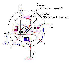
In the PM type stepper motor, a permanent magnet is used for rotor and coils are put on stator. The stepper motor model which has 4-poles is shown in the figure on the left. In case of this motor, step angle of the rotor is 90 degrees.
As for four poles, the top and the bottom and either side are a pair.  coil, coil,  coil and coil and  coil, coil,  coil correspond respectively. For example, coil correspond respectively. For example,  coil and coil and  coil are put to the upper and lower pole. coil are put to the upper and lower pole.  coil and coil and  coil are rolled up for the direction of the pole to become opposite when applying an electric current to the coil are rolled up for the direction of the pole to become opposite when applying an electric current to the  coil and applying an electric current to the coil and applying an electric current to the  coil. It is similar about coil. It is similar about  and and  , too. , too.
The turn of the motor is controlled by the electric current which pours into  , ,  , ,  and and  . The rotor rotational speed and the direction of the turn can be controlled by this control. . The rotor rotational speed and the direction of the turn can be controlled by this control.

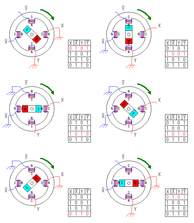
 Clockwise control Clockwise control
 |
 , ,  , ,  and and  are controlled in the following order. are controlled in the following order.
 |  |  |  | Step angle |
| 0 | 1 | 0 | 1 | 0° |
| 1 | 0 | 0 | 1 | 90° |
| 1 | 0 | 1 | 0 | 180° |
| 0 | 1 | 1 | 0 | 270° |
"0" means grounding. |

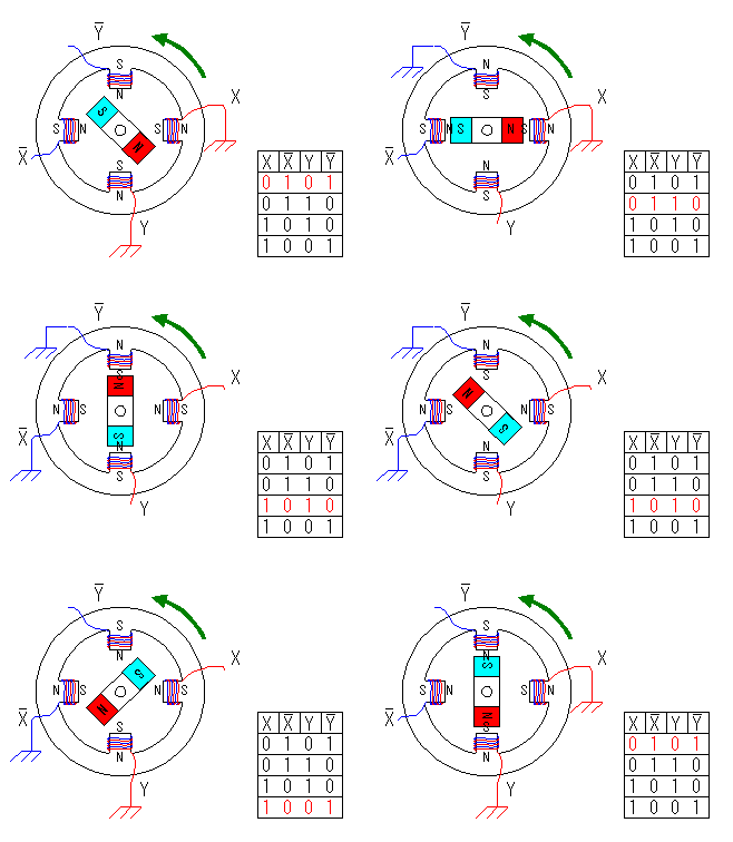
 Counterclockwise control Counterclockwise control
 |
 , ,  , ,  and and  are controlled in the following order. are controlled in the following order.
 |  |  |  | Step angle |
| 0 | 1 | 0 | 1 | 0° |
| 0 | 1 | 1 | 0 | -90° |
| 1 | 0 | 1 | 0 | -180° |
| 1 | 0 | 0 | 1 | -270° |
"0" means grounding. |
You can find by the figure, the rotor is stable in the middle of 2 poles of stator. When one side of the stator polarity is changed, the bounce by the magnetism occurs. As a result, the direction of rotor's turn is fixed.
The characteristic of stepper motor is the angle can be correctly controlled and to be stable rotates ( It is due to the reliability of the control signal ). Moreover, because the rotor is fixed by the magnetism in the stationary condition as shown in the principle, the stationary power(Stationary torque) is large. It suits the use to make stop at some angle.
The motor which was used this time is 48 steps and the step angle is 7.5 degrees.
The way of controlling is the same as the previous example completely. It operates when controlling the electric current of  coil, coil,  coil, coil,  coil and coil and  coil. coil.
The case of the clockwise control is shown below.
The combination of  , ,  , ,  and and  repeats four patterns. repeats four patterns.
 |  |  |  | Step angle |
| 0 | 1 | 0 | 1 | 0.0° |
| 1 | 0 | 0 | 1 | 7.5° |
| 1 | 0 | 1 | 0 | 15.0° |
| 0 | 1 | 1 | 0 | 22.5° |
| 0 | 1 | 0 | 1 | 30.0° |
| 1 | 0 | 0 | 1 | 37.5° |
| 1 | 0 | 1 | 0 | 45.0° |
| 0 | 1 | 1 | 0 | 52.5° |
| 0 | 1 | 0 | 1 | 60.0° |
| 1 | 0 | 0 | 1 | 67.5° |
| 1 | 0 | 1 | 0 | 75.0° |
| 0 | 1 | 1 | 0 | 82.5° |
| 0 | 1 | 0 | 1 | 90.0° |
| 1 | 0 | 0 | 1 | 97.5° |
| 1 | 0 | 1 | 0 | 105.0° |
| 0 | 1 | 1 | 0 | 112.5° |
| 0 | 1 | 0 | 1 | 120.0° |
| 1 | 0 | 0 | 1 | 127.5° |
| 1 | 0 | 1 | 0 | 135.0° |
| 0 | 1 | 1 | 0 | 142.5° |
| 0 | 1 | 0 | 1 | 150.0° |
| 1 | 0 | 0 | 1 | 157.5° |
| 1 | 0 | 1 | 0 | 165.0° |
| 0 | 1 | 1 | 0 | 172.5° |
|  |
 |  |  |  | Step angle |
| 0 | 1 | 0 | 1 | 180.0° |
| 1 | 0 | 0 | 1 | 187.5° |
| 1 | 0 | 1 | 0 | 195.0° |
| 0 | 1 | 1 | 0 | 202.5° |
| 0 | 1 | 0 | 1 | 210.0° |
| 1 | 0 | 0 | 1 | 217.5° |
| 1 | 0 | 1 | 0 | 225.0° |
| 0 | 1 | 1 | 0 | 232.5° |
| 0 | 1 | 0 | 1 | 240.0° |
| 1 | 0 | 0 | 1 | 247.5° |
| 1 | 0 | 1 | 0 | 255.0° |
| 0 | 1 | 1 | 0 | 262.5° |
| 0 | 1 | 0 | 1 | 270.0° |
| 1 | 0 | 0 | 1 | 277.5° |
| 1 | 0 | 1 | 0 | 285.0° |
| 0 | 1 | 1 | 0 | 292.5° |
| 0 | 1 | 0 | 1 | 300.0° |
| 1 | 0 | 0 | 1 | 307.5° |
| 1 | 0 | 1 | 0 | 315.0° |
| 0 | 1 | 1 | 0 | 322.5° |
| 0 | 1 | 0 | 1 | 330.0° |
| 1 | 0 | 0 | 1 | 337.5° |
| 1 | 0 | 1 | 0 | 345.0° |
| 0 | 1 | 1 | 0 | 352.5° |
|
|
|


