Parts explanation
of Ultrasonic Range Meter unit
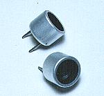 I used the ultrasonic sensor for the air which is made by the Nippon Ceramic company. This sensor separates into the two kinds for the transmitter and the receiver. For the transmitter, it is T40-16 and for the receiver, it is R40-16. T shows the thing for the transmitter and R shows the thing for the receiver. 40 shows the resonant frequency of the ultrasonic.(40KHz) 16 shows the diameter of the sensor. I used the ultrasonic sensor for the air which is made by the Nippon Ceramic company. This sensor separates into the two kinds for the transmitter and the receiver. For the transmitter, it is T40-16 and for the receiver, it is R40-16. T shows the thing for the transmitter and R shows the thing for the receiver. 40 shows the resonant frequency of the ultrasonic.(40KHz) 16 shows the diameter of the sensor.Because the one of the terminal is connected with the case, when grounding, it uses the terminal on the side of the case. 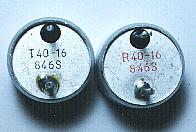 The specification of the ultrasonic sensor is shown below.
As for the detail specification, refer to "Air Transmission Ultrasonic Sensor".  This is the IC which is often used for the timer, the oscillator. This time, it is used for the oscillation of the transmission timing pulse and the oscillation of the ultrasonic frequency.  This IC is the IC of the CMOS which the six inverters are housed in. At the transmitter circuit, it is mainly used for the drive circuit of the ultrasonic sensor. At the receiver circuit, it is used for the oscillation of the measurement pulse in the ultrasonic reception time and is used to arrange the wave from of the counter control pulse.  This IC is the low noise operational amplifier. It is used for the amplification of the received ultrasonic signal. The low noise type operational amplifier must be used because it does the about 60dB (1000 times) amplification. LM833 can be used as the IC.  This IC is the single power supply-type operational amplifier. This IC is used for the detection of the received signal. The comparator can be used.  As for this IC, the four NAND circuits of 2 inputs are accommodated. It is used to compose SR-FF and to measure the reaching time of the ultrasonic.  This is the BCD counter for the 3 digits. It counts the measurement pulse in the reaching time of the ultrasonic. It has the controlling function to display the LED about the 1 digit, too.  It makes the signal for the 7 segment LED drive by the input of the binary-coded decimal code(BCD).  The stable +9V can be gotten from +12V to +30V input by this IC. The maximum output current is 100 mA. In the measurement, the maximum power supply electric current of the circuit this time was to about 70 mA be. 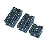 The equipment which was made this time used the sockets for the ICs mounting. It is to adjust in the order. Especially, because IC1 is removed in the adjustment of the ultrasonic frequency, it had better install using the socket.  This transistor is used to control the 7 segment LED in the lighting-up. It uses the PNP type because it controls the cathode side of the LED. 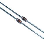 This diode is used to detect the received ultrasonic. The ultrasonic frequency is about 40 KHz, so, the diode with the good high frequency characteristic is used. 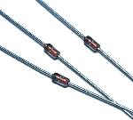 This diode is used for the mask of the transmission pulse and the part which the pulse for the counter control is composed of. It is not the special diode. 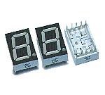  This is the high brightness 7 segment LED which is made by the Stanley company in Japan. It has the 12-mm width, the 19-mm height, the 8-mm depth. 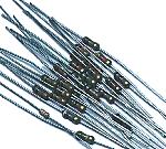 It is OK with the one that the permission electric power of the resistor is 1/8 W. I used as follows in the relation of the mounting space. 1/8 W were used to mount levelly. 1/4 W were used to mount perpendicularly. 1/8 W of all are OK. 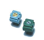 These are the small variable resistors. These are used for the adjustment of the ultrasonic frequency and the frequency adjustment by the measurement pulse. 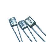 These are the film capacitors of the polyester. They are used as the capacitors of the oscillator. It's OK even if you use the ceramic capacitors. 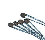 These are the disk-type ceramic capacitors. Because the high frequency characteristic is good, these are used as the coupling capacitors(It cuts the direct current but it lets through the alternating current) of the ultrasonic signal amplification. 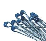 These are used as the bypass capacitors. It is small size but it has the comparatively big capacity(0.1µF). 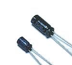 These are used as the ripple filter capacitors of the power circuit. There is polarity. So, Be careful so as not to make a mistake when mounting them. 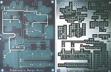 I used the double sided printed board. As for the way of making the printed board, refer to "Manufacturing of Original PCB". 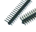 These terminals are used for the wiring with the outside parts such as the power supply wiring. Two lines of the terminals are used to put the ultrasonic sensor. 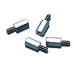 These studs are used to install the equipment in the case. Choose the length of stud for the ultrasonic sensor to become case approximately central. This time, I used the one with the 10-mm length. |
|||||||||||||||||||||