Parts explanation
for the ultrasonic alarm (2)
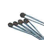
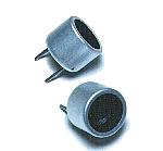 I used the ultrasonic sensor for the air which is made by the Nippon Ceramic company. This sensor separates into the two kinds for the transmitter and the receiver. For the transmitter, it is T40-16 and for the receiver, it is R40-16. T shows the thing for the transmitter and R shows the thing for the receiver. 40 shows the resonant frequency of the ultrasonic.(40KHz) 16 shows the diameter of the sensor. The brief specification of the ultrasonic sensor is shown below.
As for the detail specification, refer to "Air Transmission Ultrasonic Sensor". |
||||||||||||||||||||||
 This is the IC which is often used for the timer, the oscillator. This time, the CMOS type is used but the bipolar type is OK. This time, it is used for the oscillation of the transmission timing pulse, the oscillation of the ultrasonic frequency, the gate circuit of the alarm detector and the output circuit. |
 This IC is the IC of the CMOS which the six inverters are housed in. This IC is mainly used for the drive circuit of the ultrasonic sensor. |
|||||||||||||||||||||
 This IC is the low noise operational amplifier. It is used for the amplification of the received ultrasonic signal. The low noise type operational amplifier must be used because it does the about 60dB (1000 times) amplification. |
 This IC is the single power supply-type operational amplifier. This IC is used for the detection of the received signal. The comparator can be used. |
|||||||||||||||||||||
 As for this IC, the four NAND circuits of 2 inputs are accommodated. It is used to compose SR-FF and to measure the reaching time of the ultrasonic. |
 The stable +9V can be gotten from +12V to +30V input by this IC. The maximum output current is 100 mA. |
|||||||||||||||||||||
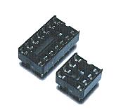 The equipment which was made this time used the sockets for the ICs mounting. It is to adjust in the order. Especially, because IC1 is removed in the adjustment of the ultrasonic frequency, it had better install using the socket. |
 This is the transistor with the general NPN type for the small signal amplification. It is used for the drive circuit of the relay. If the collector electric current is the equal to or more than 100-mA one with the general NPN-type transistor for the small signal, the other transistor is OK. |
|||||||||||||||||||||
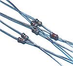
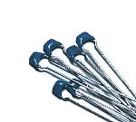
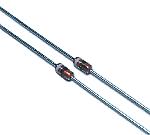 This diode is used to detect the received ultrasonic. The ultrasonic frequency is about 40 KHz, so, the diode with the good high frequency characteristic is used. |
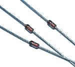 This diode is used for the mask of the transmission pulse and used to prevent from transistor destruction by the back electromotive force of the relay. It is not the special diode. |
|||||||||||||||||||||
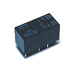 I used the relay to output the alarm outside. I used the relay to output the alarm outside.I used the one that the drive voltage is DC 12 V . There are two sets of points of contact. The specification is shown below respectively. 125V AC : 0.6A 110V DC : 0.6A 30V DC : 2A |
 At the circuit this time, the resistors that the permission electric power of the resistor is 1/8 W are used. |
|||||||||||||||||||||
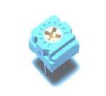 This is a small semi fixed resistor. This is used for the adjustment of the ultrasonic frequency. |
 These are the disk-type ceramic capacitors. Because the high frequency characteristic is good, these are used as the coupling capacitors(It cuts the direct current but it lets through the alternating current) of the ultrasonic signal amplification. |
|||||||||||||||||||||
 These are used as the bypass capacitors. It is small size but it has the comparatively big capacity(0.1µF). 1000 pF are used for the high frequency circuit. |
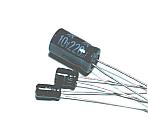 These are used for timing of 555 timer and holding of output. There is polarity. So, Be careful so as not to make a mistake when mounting them. |
|||||||||||||||||||||
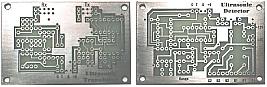 I made printed boards using positive exposure printed board for single-sided. The left side is for transducer and the right side is for detector. |
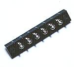
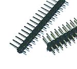 These terminals are used for the wiring with the outside parts such as the power supply wiring. Two lines of the terminals are used to put the ultrasonic sensor. |
|||||||||||||||||||||
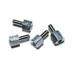 These studs are used to install the equipment in the case. The one which is made of metal because of the grounding is used. |
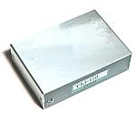 Transducer and detection unit are housed in the separate cases. Model TM-100 made by TAKACHI.,CO in Japan are used. 30mm(H), 100mm(W) and 70mm(D). |
|||||||||||||||||||||
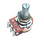 This variable resistor is used to set an alarm detection distance. This variable resistor is installed inside the case and adjusted using the screwdriver. It is because the setting distance makes not change carelessly. |
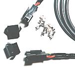 This is the cable and connector which connects transducer and detector.  |
|||||||||||||||||||||
 I put the panel which wrote the name at the back. It is the one which was printed in the color to the OHP sheet. I put in the white paper for the letter be able to be clearly seen. |
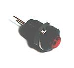 This is the LED to confirm the alarm relay operation. |
|||||||||||||||||||||
 This is the terminal to output the result which detected that the object moved. The point of contact (voltageless) of the relay is output. |
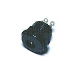 This is the connector to connect the AC adapter. The size of the connection part of the connector must use the size which is the same with the plug of the AC adapter. |
|||||||||||||||||||||
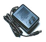 This is the power supply adapter to get DC +12V from AC 100V. The 300-mA electric current can be passed. |
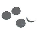 This is the leg to have put to the part in the bottom. These legs are to protect the case when putting the measurement equipment. |
|||||||||||||||||||||
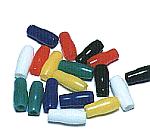 This is the cover which protects the connection part of the wiring. Because the connection part is the circuit inside, it isn't touched. I used because I looked pleasant. |
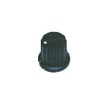 This is a knob for the alarm distance setting. The one which is fitted to the thickness of the axis of the variable resistor should be used. |
|||||||||||||||||||||