Making of the mask pattern mount Making of the mask pattern mount
The mount of the mask pattern uses the paper which is rather thinner than the thickness of the printed board. It is OK with the box of the confectionery and so on.
The thickness depends on the kind of the printed board. As for the printed board which I am using, the thickness is 1.6-mm.
I am using the paper with the 1.0-mm thickness as the mount. The one with the 1.5-mm thickness may be ideal.
When too thin, the pattern and the printed board shift and the position of the pattern doesn't become correct.
When the mount is thicker than the printed board, the crack has formed in the mask pattern sheet and the printed board. In this case, the pattern can not print beautifully.
The mount of the mask pattern |
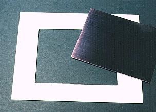
Consider the size of the clamp which holds the mask pattern and make the mount. I did to 155mm x 120mm.
Make a hole where the printed board is exactly included in the center of the mount. Make this hole carefully. The printed board makes not move. The position of the pattern has shifted when having moved. It is 100mm x 75mm that I made this time. |
Fixation of the mask pattern
Print the mask pattern of the wiring side and the component side separately beforehand to the OHP(OverHead Projector) sheet.
Fix the mask pattern of the wiring side to the mount with the glue. Fix while watching from the hole at the center and confirming the position of the pattern. Fix only the end of being one for the printed board to be able to be set in the hole.
Fix the mask pattern of the component side to the mount with the glue. Fix carefully to watch from the true top and for the position of the pattern to agree. Especially, it is necessary that the position of the through-hole agrees exactly. In case of the sheet on the component side, too, fix only the end of being one for the printed board to be able to be set in the hole.
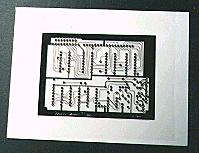
The mount and the pattern are fixed on the photograph by the stapler. However, remove if the glue dries.
The mask pattern and the printed board don't stick when there is unevenness and can not print the pattern beautifully.
|
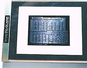
 | 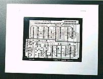 |
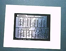
| The fixation of the wiring side pattern |
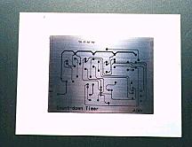
The fixation of the component side pattern
(Completion of the mask pattern mount) |
Print of the mask pattern
Set the printed board in the mount of the mask pattern, put in the clamp and fix it. As for Ultraviolet ray exposure equipment which I made, only the single side can irradiate the ultraviolet rays. It is printed in the order in the wiring side and the component side.
When doing the print on the component side, you turn the mask pattern, the mount and the printed board at the same time. Be careful so as not for the printed board to shift.
The order of the print on the wiring side and the print on the component side is OK even if it is opposite.
|