 INDF ( Indirect addressing memory ) 00h,80h,100h,180h INDF ( Indirect addressing memory ) 00h,80h,100h,180h
| This register is used when reading or writing the contents of the register with indirect addressing mode. |
 |
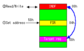
The contents of INDF become the same as the register of the address to have set to the FSR register. The addressed register with FSR can be rewritten when rewriting the contents of INDF.
INDF register is not physical register.The content of the register which FSR shows is made INDF with the mirror. You don't need thinking seriously. After setting the target register address to FSR, read or write from/to INDF. |

 TMR0 ( Timer0 count register ) 01h,101h TMR0 ( Timer0 count register ) 01h,101h
| This register is a register for the timer 0 count. A maximum of 255 counts can be set. |
 |
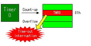
This register is counted up by the time with the hard timer. The interruption occurs when the register overflows. So, when the set value is 255, the interruption time is the shortest. It is the longest when the setting is 0.
For the details of the timer, refer to "The specification of the timer (TMR0)". |

 PCL ( Program counter Lower register ) 02h,82h,102h,182h PCL ( Program counter Lower register ) 02h,82h,102h,182h
| This is the register which stores the lower 8 bits of the program counter. |
 |
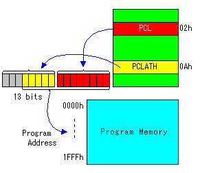
As for the program area of the PIC16 series, a maximum size is 8K words, and program address is specified by 13 bits. The lower 8 bits of the program address is stored in PCL. The upper 5 bits of the program address are stored in the PCLATH register. A program address is specified by the value which synthesized the contents of both registers.
The program memory size of PIC16F873 is 4K words. |
|