Circuit explanation of Room temperature controller
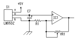 A temperature sensor (LM35DZ) can measure from 0°C to 100°C. However, the output is 0V at 2°C. Therefore, the voltage of minus is required in order to measure 0°C. Since the minus power supply is not used with this equipment, the measurable temperature is above 2°C. The output of a sensor goes up by 10mV for every 0°C. The output voltage in 32°C is 300mV. The output voltage of a sensor is amplified by an operational amplifier, and is inputted into the A/D converter of PIC. Proofreading of a temperature display is performed by adjusting the gain of an operational amplifier by VR. In this circuit, in order to simplify a circuit, the operational amplifier which operates with a plus single power supply is used. Please refer to "Operation chceck" about operation of an OP amplifier. 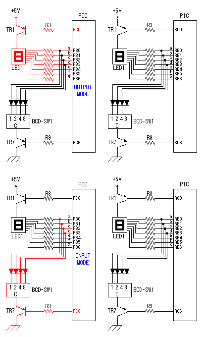 7 bits of low ranks of PORTB are used for lighting of 7 segment LED, and reading of BCD switch in common. PORTC and the 8th bit of PORTB is used for designation of a device. The mode change of PORTB is required of LED control and BCD-SW control. This change is performed by software. The diode connected to the BCD switch is for prevention of illegal current. With a BCD switch, a common terminal and each terminal corresponding to a bit short-circuit by setup. If there is no diode, the setting state of a switch will influence operation of other devices. In the case of a silicone diode, VF is about 0.6V. When L level detection of the PIC cannot be normally carried out with this voltage, it is better to change a diode into other kinds.(Germanium etc.) 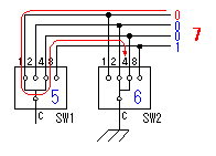 In the case of the left example, even if SW2 is set as 6, if SW1 is set as 5, the terminal 1 of SW1 is set to 0V through the terminal 4 of SW1, so a normal preset value cannot be read. 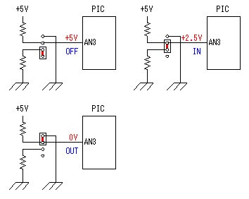 This circuit is used for the change of a display, in order to set up a temperature display in detail. Usually(Test off), although a display is 1°C unit, in the case of testing mode, it can be displayed per 0.25°C. Since the number of displays of LED is 4 digits, IN-side or OUT-side is selected. This circuit is prepared in order to perform gain adjustment of an operational amplifier more correctly. In the case of PIC16F873, ANALOG/DIGITAL designation of each PORTA port is set up by the PCFG bits of ADCON1 register. When a No. 0 port and a No. 2 port are made into an analog, a No. 3 port can be set only to an analog. Mode identifying is performed on the voltage applied to the port. 5V is OFF mode, 2.5V is IN-side mode, 0V is OUT-side mode. 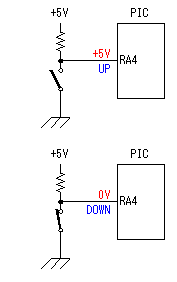 This is the circuit which changes the drive conditions of external equipment. In the case of UP mode, external equipment will be driven if room temperature becomes higher than preset temperature. In the case of DOWN mode, external equipment will be driven if room temperature becomes lower than preset temperature. 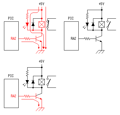 This is the circuit which controls external equipment. Although based on the drive current of the relay to be used, in this case, the drive circuit which uses a transistor is adopted. 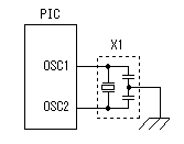 This is the oscillating circuit which makes the operation clock of PIC. The 4MHz oscillator is used with this equipment. 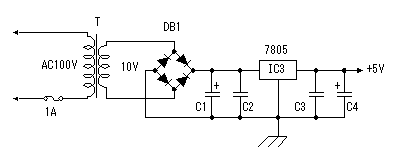 This is the circuit which makes the power supply of +5V. It is a general circuit. Although the output of a transformer was 10V AC, the output of the rectifier by a diode when 150mA flows was the voltage of about 11V DC. This is dropped on a regulator 5V. The electric power consumed by the regulator is 0.9W. (11V-5V)x0.15A=0.9W The temperature of a regulator goes up by this power consumption. Therefore, a heat sink is attached to the regulator. |