 | 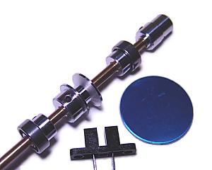 |
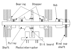
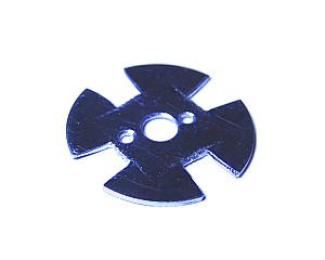
| Detection of the number of rotations of an axis is performed by a slit board and a photointerrupter. An axis is fixed to a chassis using ball bearings so that an axis may rotate smoothly. | This is in the state which attached each part temporarily. A blue disk is a slit board. The slit cannot be opened yet. The blue of an aluminum disk is a color of the sheet which has protected the surface. |
|
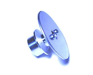 |  |
| This is in the state where the slit board was attached in the pulley. | Four slits were prepared in the slit board. Four pulses will be obtained if an axis rotates one time. |
|
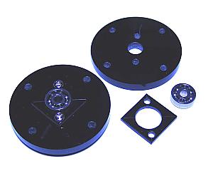 | 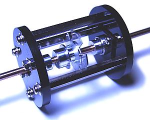 |
| Acrylics disks with a thickness of 5mm are used for rotor fixation. The hole which lets an axis pass is made in the center, and a ball bearing is attached. The acrylics board with a thickness of 1mm is used for bearing fixation. | This is in the state which assembled the rotor part. The board of both sides is being fixed with the shaft with a length of 50mm. A bearing doesn't separate because it is fixed with the stopper. |
|
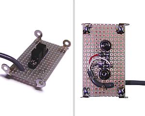 |  |
| This is the photograph of the sensor part which attached the photointerrupter on the printed circuit board. The lug terminals are soldered to the four corners of the printed circuit board. The sensor part is fixed to the rotor part with this lug terminals. The photointerrupter has four leads. A:Anode of LED, K:Cathode of LED, C:Collector of photo-transistor, E:Emitter of photo-transistor |
This is the photograph which attached the sensor part to the rotor part.
The split board is adjusted according to the position of photointerrupter.
The lug terminals are attached to the shaft which does not attach the sensor part in order to make height the same. |
|
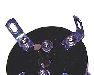 | 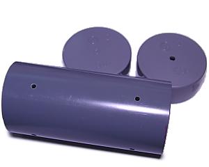 |
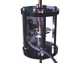
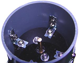
| This is the photograph furnished with the metallic ornaments for fixing the rotor part to the case. | A case is the pipe of vinyl chloride. Caps are attached in both sides. The hole for window cup shaft is made in a cap of one of the two. |
|
 | 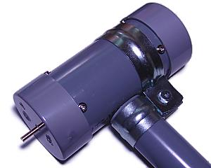 |
| This is the photograph which fixed the rotor part to the case. | This is the photograph with which the cap was attached. In order to attach a wind velocity detector, the somewhat thin pipe was used. The cable of a sensor is placed in this attachment pipe. |
|
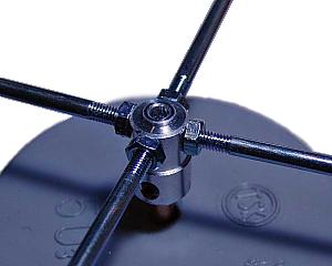 | 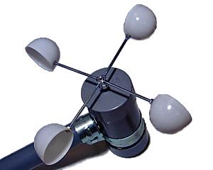 |
| This is the photograph which attached the hub in the axis. It was most serious to have made the holes for attaching shafts in this hub. Unless it makes holes correctly, the shafts cannot be attached finely. | The window cup was attached at the tip of the shaft and the detection unit was completed. Rotation of the cups was checked using the wind made with the electric fan. It seems that the cup was somewhat small. If the area which receives a wind is large, a weak wind will also rotate it. |