 Number of rotations detector circuit Number of rotations detector circuit
The photo-coupler is used in order to detect the number of rotations of a rotor which rotated by wind velocity.
In the left figure, the disk with a slit is drawn on the photo-coupler part. A horizontal line is the axis of rotator and the portion of a dotted line is a slit.
 USB drive circuit USB drive circuit

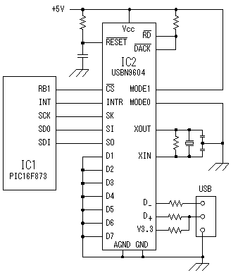
Serial interface is used for the interface of USBN9604 and PIC of the USB driver.
USBN9604 is equipped also with the parallel interface in addition to serial interface. Since high-speed transmission is unnecessary in the case of this circuit, the serial interface with few signal wires is used.
This is the interface called MICROWIRE/PLUS. With this interface, four lines, CS, SK, SI, and SO, are used. This mode is set up, when MODE1 is made into H level and it makes MODE0 L level.
An INTR line is a signal wire for the interruption control.
Since the signal wires for parallel interfaces (D1-D7) are not used in this circuit, they are grounded in order to avoid the bad influence to the circuit.
 Clock oscillating circuit Clock oscillating circuit

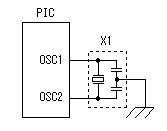
This is the oscillating circuit which makes the operation clock of PIC. The 20MHz oscillator is used with this equipment.
 Power supply circuit Power supply circuit

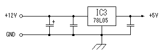
In order to supply stabilized +5V powe to the PIC and the USB driver, 3 terminal regulator is used.
The consumption current of the USB driver is about 30mA and PIC16F873 is about 10mA.. Therefore, the 100mA type regulator is used.
|