 |  |
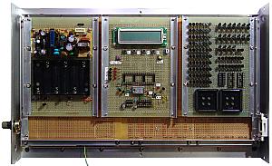
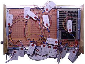
| This is in the state which carries a control unit in the back of a display panel. Wiring isn't yet done. | This is in the state of a display panel where wiring with a display control unit was attached. The length of wiring is cut according to the length to each LED. Some margins are given. Since there is much wiring, a label is attached for discernment. |
|
 |  |
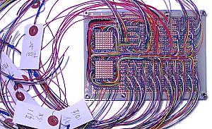
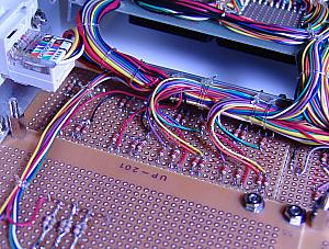
| Wiring is performed in consideration of restoration. With a lower photograph, the red wires are the wiring connected to the anode of LED. The checking is terrible, if a label is not attached before bundling. | This is in the wiring state on the back of a display control unit. Wiring is bundled with the string of vinyl. |
|
 | 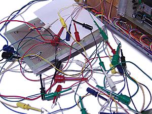 |
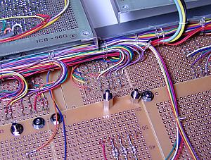
| This is in the state which attached a display control unit and wiring in the display panel. Connection by the side of LED is made after wiring of a CPU unit and a power supply unit finishes. The reason is to put the resistor which controls the brightness of LED. |
This is in the state where the resistance of LED of the 10th of second is adjusted. Seven resistors are easily exchangeable with a cable with a hook chip.
In this method, it is necessary to take care about contact of wiring. I am seldom recommended. |
|
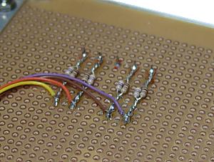 |  |
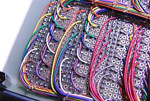
| The maximum current of large-sized LED for Hour and Minute is 25mA. Since it is a pulse drive in this circuit, it is OK even if exceeded a little. In my case, parallel connection of 100ohm and the 47ohm was carried out so that it might become about 30mA current. Since it is a pulse drive, a circuit tester cannot use for the check of current. I checked with the oscilloscope. | This is in the wiring state of LED of Year, Month and Day. A space is very narrow. I feared that a soldering iron does not touch other wiring. |
|
 | 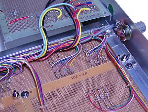 |
| This is in the wiring state of LED of a day of the week. |
This is in the wiring state of LED of a second.
The shield wire is used for wiring of a variable resister. |
|
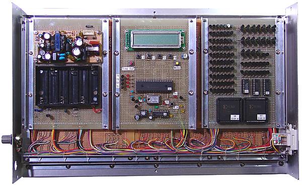 |
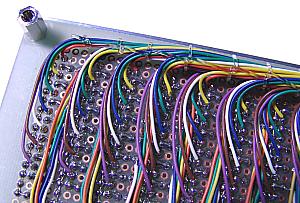
| This is in the state which all wiring finished. Wiring is being fixed to the bar under a display panel with the string of vinyl. Therefore, even if each unit is removed, a tension doesn't occur to the connection part of the LED. |
|
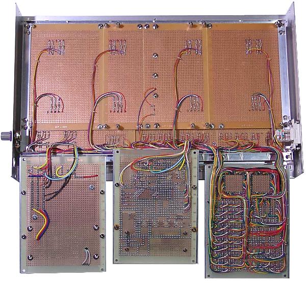 |
This is in the state which removed each unit. The wiring which has come out of each unit is also being fixed to the printed circuit board with the string of vinyl. Therefore, a tension is not produced in wiring of a printed circuit board, either.
I was perplexed in the sea of wiring until wiring of each LED finished. However, after all wiring had finished, it was able to dedicate very well shapely. |