Adjustment for DC motor speed controller
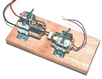 RS-380PH is used for the main motor and RE-280 is used for speed detection. Both motors are made by the MABUCHI MOTOR Inc. in Japan. Because this assembly is to adjust a speed control, both motors are directly connected using the plastic gear. When the center of both motors isn't right, there is possibility that the gear comes off the shaft of the motor. Pay attention.  The speed control flow of the circuit this time is shown with the left figure. The speed control flow of the circuit this time is shown with the left figure.At the control circuit, the following three parameters should be adjusted.
Control rate value is adjusted at the value to set to change. Control period is adjusted at the value to set to CCPR2H and CCP2L registers.  When the detection period is short and the control rate value is big, the rotating speed of the motor changes big. When the rotating speed of the motor is above the reference value, a deceleration control is done.(It reduces an drive electric current) However, because of the mass of the rotor of the motor, it doesn't react immediately. Even if it begins deceleration by the A point, the rotating speed of the motor continues to rise in a little while. In case of the B point is above the reference value, a deceleration control are done moreover. In case the speed is above the reference value, the drive electric current is increased in every period. The deceleration value at B pont is bigger than A point. Therefore, it continues to decelerate even if it falls below the reference value. When detecting rotating speed below the reference value in the C point, acceleration is begun. It is more strongly accelerated every period like the deceleration. When the detection period is short and the control rate value is big, the rotating speed of the motor changes big. When the rotating speed of the motor is above the reference value, a deceleration control is done.(It reduces an drive electric current) However, because of the mass of the rotor of the motor, it doesn't react immediately. Even if it begins deceleration by the A point, the rotating speed of the motor continues to rise in a little while. In case of the B point is above the reference value, a deceleration control are done moreover. In case the speed is above the reference value, the drive electric current is increased in every period. The deceleration value at B pont is bigger than A point. Therefore, it continues to decelerate even if it falls below the reference value. When detecting rotating speed below the reference value in the C point, acceleration is begun. It is more strongly accelerated every period like the deceleration.It repeats above mentioned operation and the rotating speed of the motor changes widely. The speed detection period is short, the turning change appears conspicuously.  When the control rate value is small, a comparatively stable speed control is done. However, the stability to the load change becomes weak. It takes time until it returns to the reference value after the rotating speed declines by the load.  You may seem to be able to do a tender control if you make a speed detection period short. However, it doesn't meet. But, this relation is in case of my control circuit. In case of the other control system, it doesn't apply. You may seem to be able to do a tender control if you make a speed detection period short. However, it doesn't meet. But, this relation is in case of my control circuit. In case of the other control system, it doesn't apply.In case of my control circuit, it increases a deceleration value or an acceleration value every period. Even if a control electric current is changed, the rotating speed doesn't sometimes change immediately. This is because of the mass of the rotor. When the speed detection period is short, the motor drive electric current changes widely. As a result, the change of the rotating speed becomes big. When the detection period is long, the band of the drive electric current becomes small. As a result, the change of the rotating speed becomes small. When the detection period is long, the controllability to the load change declines. However the bad influence comes out when too long. 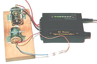 A power is turned on after connecting a motor and a control system. It turns on the motor first and after that, it turns on the controller. When the power of the motor and the control circuit is the same, it isn't made. The reason for turning on the power in the order is hereinafter. When turning on the controller first, because voltage isn't applied to the speed detector, the control circuit increases a drive electric current and becomes a maximum drive electric current condition finally. When turning on the power of the motor in this condition, a motor is driven in the maximum electric current. As a result, the motor becomes reference speed gradually after beginning to turn forcefully. When this operation is not a problem, you don't have to be conscious of the turning on order. You consider the above and adjust the control parameter. It is troublesome a little.
It adjusts by the value of CCPR2H and the CCP2L registers.
It adjusts by the value of speed. To change the speed range to adjust with the variable resistor, the value of R12 should be changed.
It adjusts by the value of change. Please try variously because these values change with the motor and the detector to use. |