Installation of LED bar Installation of LED bar
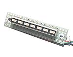
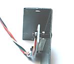
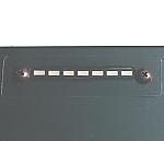
An LED bar is mounted on the lid of the case. First, it makes a rectangular hole to mount the displaying part of the LED on the case. The case which I used is made from aluminum. Therefore, I adjust the size of the hole using the jigsaw and the files. An LED bar is protected with the transparent acrylic panel with the thickness of 0.5 mm. Screws are used for the fixation of the acrylic panel and the LED bar.
Open the holes
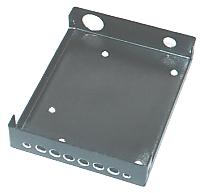
The holes are made which install a motor connection terminal, a variable resistor for the motor speed setting and a power suupply connector on the side of the case. Also, the holes are opened which installs control unit and an FET at the bottom. These holes are made while the size of the parts are measured.
The confirmation is needed that the variable resistor and the power suupply connector don't touch to the control unit.
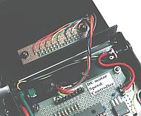
Installation and wiring for motor connection terminal and FET
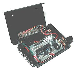
The back panel is installed with the motor connection terminal. Because the place of the wiring is narrow, wiring to a terminal and an FET is done before installing of control unit. A terminal cover is put to the central terminal (the drain) of the FET. It is to prevent from touch among the terminals.
Installation and wiring for variable resistor and power suupply connector
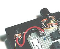
The back panel is installed with these parts. I removed the stopper of the variable resistor used the needle plier. A knob is installed so as not touch with the screw part of the variable resistor. When the axis of variable resistor is long, it makes short.
Because the wiring part of these parts is narrow too, wiring to the terminals are done before installing control unit.
Installation and wiring for control unit
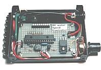
Control unit is installed after all wiring is ended to the parts which were installed on the side of the case. Wiring is done in the order from the difficult place. I wired from the grounding wire and the power supply wire. It is because those wires are thick. Next, FET gate wire  Variable resistor wire Control voltage wire. Variable resistor wire Control voltage wire.
The FET has the possibility to generate heat. Therefore, need an attention to wire doesn't touch with the FET.
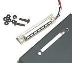
Installation of name plate
I installed a name plate on the lid.
An attention is needed so as not for the installing screw to do touch with the control unit.
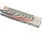
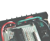
Wiring for LED bar
Wiring with the LED bar to have put to the lid is done. Because there are many numbers of the wires, it pays attention so as not to make a mistake. I wired in order of 8 7 6 5 4 3 2 GL. As for the length of the wiring, it considers a situation which opened a lid. To prevent the touch of the wiring with the FET when closing a lid, wiring is put under the control unit.
Installation of rubber legs
The equipment is complete when installing rubber legs at the bottom.
|